4-20ma Current Loop Transmitter
4-20mA Current loop is commonly used to connect process signals to a controller in industrial applications.
Sometimes, an analog voltage signal or digital communications is used, but there are many advantages to using a current loop to send process values to the controller.
In this article, we will take a closer look at the principles behind the industry standard 4…20 mA current loops.
Why use current instead of voltage ?
To understand this, we first need a fundamental understanding of current , voltage , and resistance :
- Current : Current is the flow of electrons through a circuit. A current of 1 amp equals a flow of 6.24 x 10¹⁸ electrons per second. To measure current, open a circuit and insert an amp meter into the circuit. In this way, all electrons must flow through the meter, ensuring an accurate current measurement.Unit of measurement: Amp, symbol: A.
- Resistance : Resistance is the opposition to the flow of current. If resistance increases, current flow decreases. To measure resistance, disconnect the component that has resistance from a circuit, then use an ohmmeter to measure the resistance of the component.Unit of measurement: Ohm, symbol: Ω.
- Voltage : Voltage is the difference in electrical charge between two points of a circuit. A difference in electrical charge exists if the electrons at one point are at a different energy level compared to electrons at the other point, or if there are more electrons of the same energy level at one point compared to the other point. A difference in electrical charge of 1 V is enough energy to drive 1 A current through a resistance of 1 Ω. To measure voltage, connect the voltmeter in parallel with two points of a circuit.Unit of measurement: Voltage, symbol: V.
Ohm’s Law defines how current, voltage and resistance relate to each other in a circuit:
- Current = Voltage/Resistance
- Voltage = Current x Resistance
- Resistance = Voltage/Current
To illustrate Ohm’s Law, we will have a look at a typical AA battery:
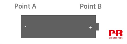
The charge at the left terminal, (Point A) is negative compared to the charge at right terminal, (point B). In this battery, the difference in charge, (the voltage), is 1.5 V.
When a circuit is connected to the battery, it creates a path for electrons to flow from the negative terminal to the positive terminal. The lamp in the following circuit has a resistance of 5 Ω. This resistance regulates the amount of current flowing through the circuit.
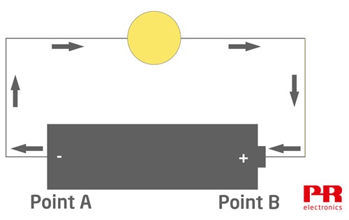
Current = Voltage/Resistance, so the current flowing around the loop is 1.5 V /5 Ω = 0.3 A.
The amount of current flow can be changed by altering the loop resistance or the loop voltage. Most current loops found in industrial applications are powered by a fixed 24 V source, so the loop current is changed by varying the opposition to current flow on the loop.
The loop transmitter
A loop transmitter measures a process variable, and regulates the loop current between 0.004 and 0.02 A, (4 mA…20 mA), by varying the opposition to current flow of the loop. Loop transmitters can measure nearly any process variable, for example temperature, pressure, level, or flow.
Also Check : 4-20mA Transmitter Animation
In the example below a loop transmitter measures a temperature sensor. The transmitter is programmed to regulate loop current flow between 4…20 mA as temperature changes from 0…100°C.
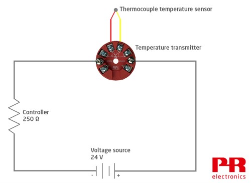
A process controller is also wired into the loop in order to measure loop current. The resistance symbol in this drawing symbolizes the controller; most have a fixed resistance of 250 Ω. The loop wire itself has some resistance as well, which should be considered when calculating a loop budget (more on that further down).
Current is common in a series circuit, so the loop current regulated by the transmitter and the current that is measured by the controller are identical.
Also Read : Basics of 4-20mA Loops
Electromagnetic interference
To ensure accurate process measurements, it is important to minimize error due to electromagnetic interference (EMI) . EMI is commonly found in industrial environments, and some sources are: Variable frequency drives, soft starters, across the line contactors, mobile radios, 50/60 Hz noise from power mains, generator slip rings, DC motor commutators, and electrostatic discharge created within the process or by lightning.
Current signals are inherently more immune to EMI than voltage signals, especially over longer distances. This is one of the big advantages of using current instead of voltage to get process measurements to a control system. Other reasons for why 4…20 mA is a widely established standard for use in process control are:
- Voltage signals attenuate slightly over long distance because of wire resistance. This is especially problematic if the signal level is low (e.g. mV outputs from load cells). Unlike voltage signals, 4… 20 mA current signals do not attenuate over a long distance (within limits). It does not matter if the process sensor is separated from the controller by 5 m, 100 m or even more. The current flow regulated by the transmitter is correct and identical everywhere on the current loop.
- A broken wire on a current loop results in a 0 mA current flow. A controller can easily detect this unusually low current level as a cable error. If voltage signals are used, broken wiring can act like an antenna, allowing local EMI to induce a voltage onto the signal wires. This makes it more difficult to detect a cable break if the controller is measuring voltage.
- You can program most current transmitters to regulate current to an unusually high or low level if the sensor fails. For example, the transmitter can regulate loop current to 3.5 or 23 mA if the thermocouple sensor breaks.
Loop budget
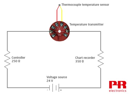
In the previous example, the transmitter regulates current flow on a loop that is powered by 24 V, and has one other device, the controller, wired into the loop.
Now, if we add a chart recorder to the loop, we have to find out if the loop will still work correctly with the additional 350 Ω resistance. To do this out, we calculate a loop budget.
How to make a loop budget:
First, we determine the maximum current in the loop. In this example, the transmitter is configured to increase loop current to 23 mA if a sensor error occurs. Therefore, the maximum current throughout the loop is 0.023 A.
Ohm’s Law states: Voltage = Current x Resistance. Therefore:
- The controller loop voltage requirement is: 0.023 A x 250 Ω = 5.75 V .
- The chart recorde r loop voltage requirement is 0.023 A x 350 Ω = 8.05 V .
The transmitter data sheet shows it requires at least 8 V to energize.
Finally, the lenght of the wire has to be considered. In this example, the distance between transmitter and controller/chart recorder is 40 meters. Thus, the total loop wire length is 80 meters. Assuming wires with a cross sectional area of 0.445 mm² are used, the total loop wire resistance is 10.7 Ω. Using Ohm’s Law: 0.023 A x 10.7 Ω = 0.25 V .
Now, subtract all the voltage drops from the loop voltage source:
| Loop voltage | 24 V |
|---|---|
| Voltage required by the controller | -5.75 V |
| Voltage required by the chart recorder | -8.05 V |
| Voltage required to energize the transmitter | -8 V |
| Voltage required by the loop wire resistance | -0.25 |
| Voltage remaining to power other loop loads | 1.95 V |
After calculating our budget, we now know that this loop has more than enough voltage to drive 23 mA through all loop loads in case of a sensor error occur.
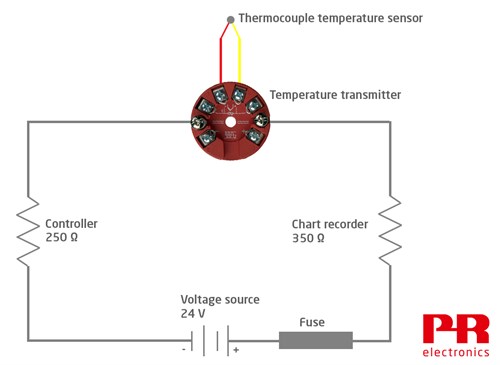
Fuse protection
The loop should always be protected from short circuit current by adding a fuse to the loop. This fuse protects the loop from excessive current, if a short circuit occurs that bypasses the 4…20 mA current regulation provided by the transmitter. Loop current will drop to 0 mA if the fuse blows, as a result the controller and chart recorder will detect this unusually low current value as error.
2-wire transmitters vs. 4-wire transmitters
The transmitters discussed so far are so-called “2- wire” transmitters. A 2-wire transmitter is energized by the loop power supply, which is why it is sometimes called a “loop powered” transmitter.
Some advantages of 2-wire transmitters:
- Separate power wires are not required in the installation
- Lower cost
- They can be located in the sensor head (i.e. very close to the sensor)
- They have very low power consumption
However, depending on your needs, 4-wire transmitters can be the better choice.
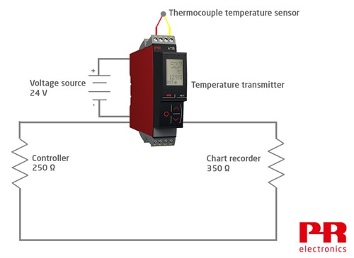
In this example, the 24 V source is connected to the transmitter. Some of its power is used to directly energize the transmitter, while additional power is used to energize the 4…20 mA current loop.
Some advantages of 4-wire transmitters:
- There is enough power available to allow additional transmitter features, like contact outputs and an integral display
- Enough power is available to allow a higher level of sensor excitation; e.g., nearly all load cell transmitters are 4-wire transmitters, because each load cell typically requires 10 V at 29 mA excitation
- 4-wire transmitters can be energized by AC or DC voltage, while loop powered transmitters are energized by DC voltage only
Also Read : 4-20mA Transmitter Troubleshooting
Active vs. passive current
Devices on a current loop are either active or passive. “Active” in this context means that a device has a voltage source that powers the loop. There can only be one active device on a current loop. “Passive” devices are the exact opposite – they do not have their own voltage source and therefore are dependent on an external source.
Source : prelectronics