Advantages and Disadvantages of 4-20mA Current Loop
While we’ve reviewed some of the fundamentals of 4-20mA two-wire current loops and the basic loop elements, and we have an idea of how they work together, let’s consider some of the advantages of 4-20mA signal transmission…
Probably the greatest advantage of using a current loop for signal transmission is the current loop’s low sensitivity to electrical noise. This is very important for long distance transmission in harsh industrial environments.

As a generally low impedance system, it is much less sensitive to induced noise, than perhaps the high impedance input of a voltage amplifier. The currents injected by typical noise sources are generally no more than a few hundred micro-amps, usually insignificant to the 16mA span.
The use of a “Live Zero” also improves the signal to noise ratio at low levels, allowing us to accurately discern low signal levels without added noise or interference.
Also Read : 4-20mA Transmitter Loop Checks
Another advantage to the 4-20mA current loop is that it is essentially lossless with respect to the transmission media (wire) and the interconnections (connectors). That is, the accuracy of the signal is not affected by the voltage drop in the interconnecting wiring. This allows the signal transmission to occur over long distances, with varying conductors.
Compare this to voltage signals, which will always have an associated signal loss related to the length of the wires— the 4-20mA signal current does not exhibit any signal losses under this same scenario.
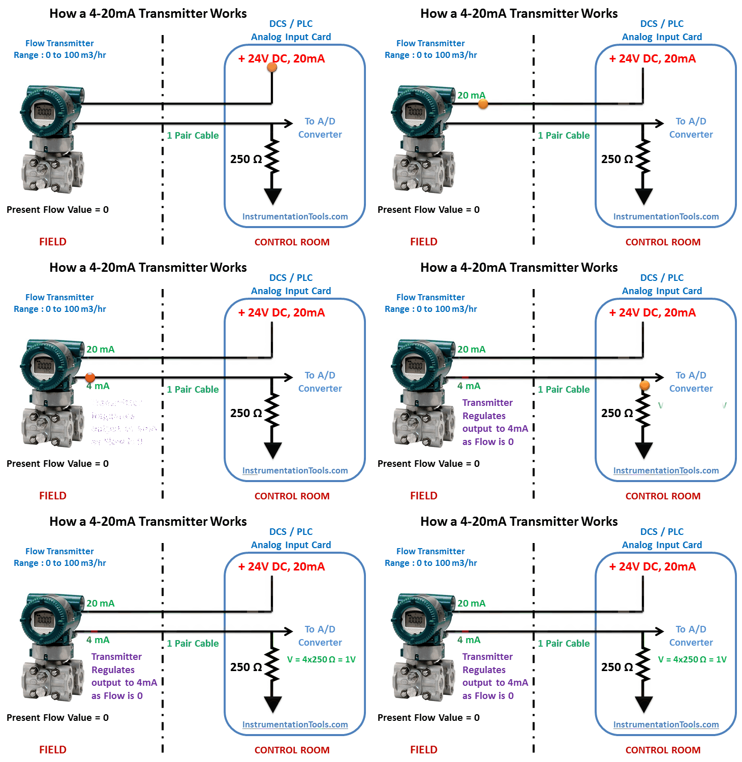
Kirchoff’s Current Law teaches us that the current in a loop is equivalent at any point in the loop. That is, if you happen to be reading 12mA at your receiver input, you can be certain that 12mA is passing through your transmitter.
Also Read : 4-20mA Transmitter Alarm Limits
The 4mA “Zero-Offset”, “Live Zero”, or “Positive-Zero” is Failsafe. The use of 4mA as the starting point for our transmitted signal is useful in trouble-shooting, as signal integrity is verified with 0% of input and output signal.
A failed current loop due to a lead break or open device can be immediately discerned as zero current flow, which is a fail-safe level outside of the signal range.
By offsetting the signal from zero, some transmitters will define an alarm limit just below 4mA and different from zero, allowing a receiver to detect other failures in the system, like an input sensor lead break.
Having a live zero in your control system also allows you to set the “zero” of your controlled device (i.e. an actuator valve or other device) just a little bit below 4mA to hold it completely OFF.
You wouldn’t be able to do that with a zero-based 0-20mA output. A “Live Zero” of 4mA also permits the two-wire current loop to power the transmitter, simplifying installation and reducing costs.
Also Read : 4-20mA Transmitter Wiring
The 4-20mA current loop also allows additional “Receiver” devices to be connected in series in the loop without a loss of signal. That is, as long as the loop voltage supply has sufficient capacity to drive the additional IR voltage drops of the added devices, and its voltage does not exceed the maximum voltage rating of the transmitter.
For example, you might choose to wire a panel meter, a trend recorder, and a PLC input card in series in the same current loop.
The loop transmitter will maintain proper current in the loop, up to the voltage capability of the loop. The number of additional receiver devices you can add is only limited by the available voltage level.
The 4-20mA transmission standard also has low inherent energy, minimizing its ability to couple noise into other systems and also reducing its radiated emissions.
Contrast that to the older pneumatic systems that use inefficient high power compressors up to 50HP to drive compressed air through their control lines.