What are the requirement of Flow Conditioner in flow measurement ? Advantages and Disadvantages of Flow Conditioners and impact of flow conditioner on flow meters.
Flow Conditioner in Flow Measurement
When dealing with flow measurement, we cannot simply stick a flow meter in the pipe, turn it on and expect perfect results.
In the real world, we have to deal with:
- Installation effects
- Swirl
- Flow profile distortion
- Pulsation
- Noise
All of these combine in different ways to generate measurement errors!
Fully Developed Flow
- Fully developed pipeline flow is the ideal state of a fluid in a pipe.
- If we had an infinitely long pipe, this is the flow we would always see.
- It is mathematically predictable.
- It is perfectly symmetrical around the center of the pipe.
- It has no swirl.
- This should guarantee us perfect, error free, repeatable measurement.
- Installation effects take us away from this state.
Swirl
- Swirl is the rotation of fluid in a pipe.
- It is caused by any change in piping direction!
- It can also be caused by any partial restriction of a pipe.
- Swirl causes unpredictable distortions in the flow profile that change over time.
- Swirl flattens and then inverts flow profiles due to centripetal force. The harder the fluid is spinning, the more energy that is pushed to the pipe walls.
- Swirl can cause local effects due to the location of pressure taps (dP measurement) or in the case of Ultrasonic Meters (adding to or subtracting to local path velocity).
Installation Effects
Every pipe fitting generates an installation effect.
- Tees
- Elbows
- Expanders
- Reducers
- Valves
- Probes
All of these objects can combine to create a deviation from perfect fully developed flow.
Measurement Errors
- The further we get from our perfect, swirl free, fully developed flow, the more uncertain our measurement becomes.
- Error due to flow profile distortion – deviation from baseline state.
- Error due to swirl itself.
- What if we want to shorten our meter run?
- What do we do?
Without Flow Conditioning
- We can build a meter run without any sort of flow conditioning!
- It just needs to be very long to compensate for installation effects and swirl.
- AGA3-2000 even allows this.
Meter Types
- All volumetric flow meters can be flow conditioned: Orifice, Ultrasonic, Venturi, Coriolis Vortex, Turbine, Cone, Mag, etc.
- Every meter type responds differently to the effects of swirl and flow profile distortion.
- Volumetric flow meters are looking for ‘good flow’. Flow with minimal swirl and good flow profiles.
- A flow conditioner is simply trying to improve the flow that the meter is seeing.
It’s far easier to measure good flow with a bad meter, than trying to measure bad flow with a good meter
Orifice Meters
- A thin plate with a very sharp chamfered hole creates a significant pressure drop.
- The flow rate of the fluid is proportional to the pressure drop.
- So why is there a problem?
Tube Bundles & Straightening Vanes
- Tube bundles can be very problematic in custody transfer applications.
- AGA3 test data has shown them to be have very unpredictable behavior in scenarios with various upstream configurations.
- A low pressure drop combined with a long length (2 – 3D) result in an inability to properly redistribute the flow profile, while locking in distortions.
- Testing has found tube bundles to cause errors in straight pipe baseline scenarios!
- AGA3 itself shows in table 2-8 that there are configurations where a tube bundles cannot even be used!
Cone Meters
- Similar to other dP devices.
- Have a high pressure and a low pressure tap.
- Has a unique geometry that forces flow to the outside of the pipe.
- High pressure tap is in a similar location as with a orifice plate or venturi, but low pressure tap is in the center of the element geometry.
- Supposed to be highly immune to installation effects and swirl, requires only 0 – 3 upstream pipe diameters and no flow conditioning.
Ultrasonic Meters
- Rely on a noise pulse that is transmitted through the fluid and the flow rate is computed using the transit time.
- Transit time is affected by velocity disturbances within the pipe, slowing or speeding up the pulse.
- Multiple paths help to generate a complete picture of the cross sectional flow within the pipe.
- The meter only knows how long it took for the pulse to travel from point A to point B.
- It cannot guess the state of the flow along the way.
Pressure Drop
- All fittings, obstructions, even pipe itself has a “k factor”.
- The k factor is the pressure loss coefficient for a particular piece of piping.
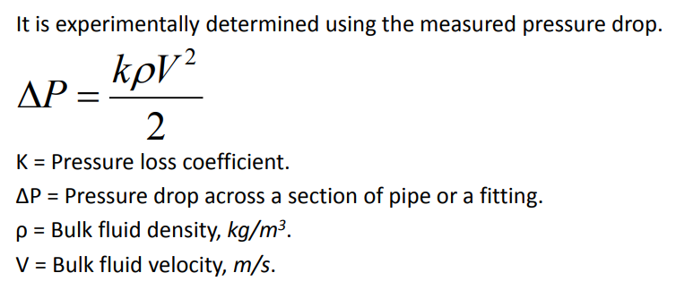
- For natural gas applications, most plate flow conditioners have a K factor of approximately 2.
- Tube bundles are closer to 0.75 – 1.5.
- What if we are worried about the pressure drop across the flow conditioner?
Flow Conditioning Conclusion
- Can eliminate up to 80 – 90% of pipeline swirl.
- Help restore flow profile symmetry and eliminate distortions.
- Isolates the flow meter from upstream disturbances.
- Allows much shorter meter runs to be used with much higher repeatability.
- Are applicable for all liquid or gas flows! The flow conditioner is merely helping out the meter, providing higher reproducibility and lower uncertainty!