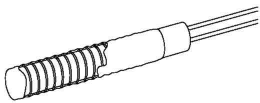
RTDs are sensors used to measure temperature by correlating the resistance of the RTD element with temperature. Most RTD elements consist of a length of fine, coiled wire wrapped around a ceramic or glass core. The element is usually quite fragile, so it is often placed inside a sheathed probe to protect it.
The RTD element is made from a pure material: platinum, nickel or copper. The material has a predictable change in resistance as the temperature changes; it is this predictable change that is used to determine temperature. There are three main categories of RTD sensors; thin film, wire-wound, and coiled elements. While these types are the ones most widely used in industry, there are some places where other more exotic shapes are used, for example, carbon resistors are used at ultra low temperatures.
Carbon resistor elements are widely available and are quite inexpensive. They have very reproducible results at low temperatures. They are the most reliable element at extremely low temperatures. They do not generally suffer from significant hysteresis or strain gauge effects.
Strain free elements use a wire coil that is minimally supported within a sealed housing filled with an inert gas. These sensors are used up to 961.78°C and are used in the standard platinum resistance thermometer (SPRT)’s that define International Temperature Scale (ITS)-90. They consist of platinum wire loosely coiled over a support structure so the element is free to expand and contract with temperature, but they are very susceptible to shock and vibration as the loops of platinum can sway back and forth causing deformation.
Thin film elements have a sensing component that is formed by depositing a very thin layer of resistive material, normally platinum, on a ceramic substrate. This layer is usually just 10 to 100 angstroms thick. It is then coated with an epoxy or glass that helps protect the deposited film and also acts as a strain relief for the external lead-wires.
Disadvantages of thin film elements are that they are not as stable as their wire wound or coiled counterparts; and they can only be used over a limited temperature range due to the different expansion rates of the substrate and resistive deposited giving a strain gauge effect that can be seen in the resistive temperature coefficient. These elements work with temperatures to 300°C.
Wire-wound elements can have greater accuracy, especially for wide temperature ranges. The coil diameter provides a compromise between mechanical stability and allowing expansion of the wire to minimize strain and consequential drift. The sensing wire is wrapped around an insulating mandrel or core. The winding core can be round or flat, but must be an electrical insulator. The coefficient of thermal expansion of the winding core material is matched to the sensing wire to minimize any mechanical strain.
Strain on the element wire will result in a thermal measurement error. The sensing wire is connected to a larger wire, usually referred to as the element lead or wire. This wire is selected to be compatible with the sensing wire so that the combination does not generate an EMF that would distort the thermal measurement. These elements work with temperatures to 660 °C.
Coiled elements have largely replaced wire-wound elements in industry. This design has a wire coil which can expand freely over temperature, held in place by some mechanical support which lets the coil keep its shape. This strain free design allows the sensing wire to expand and contract free of influence from other materials; in this respect it is similar to the SPRT, the primary standard upon which ITS-90 is based, while providing the durability necessary for industrial use.
The basis of the sensing element is a small coil of platinum sensing wire. This coil resembles a filament in an incandescent light bulb. The housing, or mandrel, is a hard fired ceramic oxide tube with equally spaced bores that run transverse to the axes. The coil is inserted in the bores of the mandrel and then packed with a very finely ground ceramic powder. This permits the sensing wire to move while still remaining in good thermal contact with the process. These elements work with temperatures to 850°C.
Function
Resistance thermometers are constructed in a number of forms and, in some cases, offer greater stability, accuracy, and repeatability than thermocouples. While thermocouples use the Seebeck effect to generate a voltage, resistance thermometers use electrical resistance and require a power source to operate. The resistance ideally varies linearly with temperature. The platinum detecting wire needs to be kept free of contamination to remain stable.
A platinum wire or film is supported on a former so that it gets minimal differential expansion or other strains from its former, yet is reasonably resistant to vibration. RTD assemblies made from iron or copper are also used in some applications. The sensor is usually made to have a resistance of 100 Ω at 0°C.
Measurement of resistance requires a small current to be passed through the device under test. This can generate resistive heating, causing significant loss of accuracy if manufacturers’ limits are not respected, or the design does not properly consider the heat path. Mechanical strain on the resistance thermometer can also cause inaccuracy.
Lead wire resistance can also be a factor; adopting three- and four-wire, instead of two-wire, connections can eliminate connection lead resistance effects from measurements; three-wire connection is sufficient for most purposes and almost universal industrial practice. Four-wire connections are used for the most precise applications.
Advantages
The advantages of platinum resistance thermometers include
high accuracy
low drift
wide operating range
suitability for precision applications
Limitations
RTDs in industrial applications are rarely used above 660°C. At temperatures above 660°C it becomes increasingly difficult to prevent the platinum from becoming contaminated by impurities from the metal sheath of the thermometer. This is why laboratory standard thermometers replace the metal sheath with a glass construction.
At very low temperatures (for example, below -270°C), because there are very few phonons, the resistance of an RTD is mainly determined by impurities and boundary scattering and thus basically independent of temperature. As a result, the sensitivity of the RTD is essentially zero and therefore not useful.
Compared to thermistors, platinum RTDs are less sensitive to small temperature changes and have a slower response time. However, thermistors have a smaller temperature range and stability.
RTD Construction
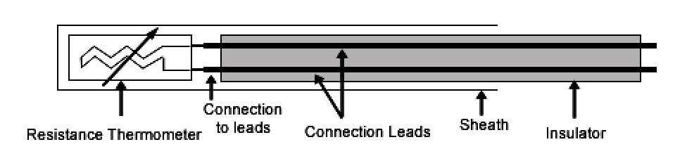
Resistance thermometer elements nearly always require insulated leads to be attached. At temperatures below about 250 °C polyvinyl chloride, silicon rubber or polytetrafluoroethylene insulators are used. At higher temperatures, glass fiber or ceramic are used.
The measuring points, and usually most of the leads, require a housing or protective sleeve, often made of a metal alloy, which is chemically inert to the process being monitored. Selecting and designing protection sheaths can require more care than selecting and designing the actual sensor, as the sheath must withstand chemical or physical attack and provide convenient attachment points.