Analogue control loop evolution
Evolution of analogue control signals
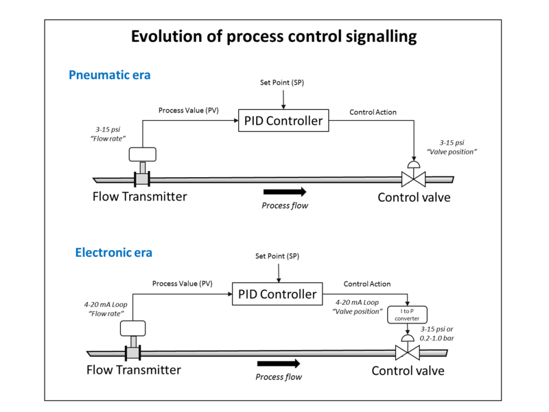
The 4–20 mA convention was born in the 1950s out of the earlier highly successful 3–15 psi pneumatic control signal standard, when electronics became cheap and reliable enough to emulate the older standard electrically. The 3–15 psi standard had the same features of being able to power some remote devices, and have a “live” zero. However the 4–20 mA standard was better suited to the electronic controllers then being developed.
The transition was gradual and has extended into the 21st century, due to the huge installed base of 3–15 psi devices. As the operation of pneumatic valves over motorised valves has many cost and reliability advantages, pneumatic actuation is still an industry standard.
To allow the construction of hybrid systems, where the 4–20 mA is generated by the controller, but allows the use of pneumatic valves, a range of current to pressure (I to P) converters are available from manufacturers. These are usually located locally to the control valve and convert 4–20 mA to 3–15 psi (or 0.2–1.0 bar). This signal is then fed to the valve actuator or more commonly, a pneumatic positioner.
The positioner is a dedicated controller which has a mechanical linkage to the actuator movement. This ensures that problems of friction are overcome and the valve control element moves to the desired position. It also allows the use of higher air pressures for valve actuation.
With the development of cheap industrial micro-processors, “smart” valve positioners have become available since the mid-1980s and are very popular for new installations. These include an I to P converter, plus valve position and condition monitoring. These latter are fed back over the current loop to the controller, using such as the HART protocol.
1 Like