Here we explained the Basic Architecture of a Programmable Logic Controller (PLC).
The input sources convert the real time analog electric signals to suitable digital electric signals and these signals are applied to the PLC through the connector rails.
These input signals are stored in the PLC external image memory in locations known as bits. This is done by the CPU
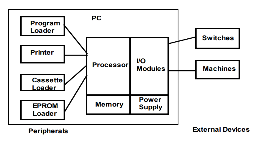
Basic Architecture of PLC
The control logic or the program instructions are written onto the programming device through symbols or through mnemonics and stored in the user memory.
The CPU fetches these instructions from the user memory and executes the input signals by manipulating, computing, processing them to control the output devices.
The execution results are then stored in the external image memory which controls the output drives.
The CPU also keeps a check on the output signals and keeps updating the contents of the input image memory according to the changes in the output memory.
The CPU also performs internal programming functioning like setting and resetting of the timer, checking the user memory
Source: gpmeham.edu.in