The principle of resistance temperature detectors (RTD) is based on the variation of electrical resistance of metals with temperature.

For this purpose several metals are used, namely, platinum, copper, nickel. When temperature increases the resistance of these metals increases. Temperature function of resistance for metals in a narrow temperature interval can be expressed by a relationship:
![]()
where:
Rϑ and R0 - are the values of electrical resistance of a metal conductor at temperatures ϑ and 0,̊C, respectively, Ohm;
α - thermal coefficient of electrical resistance, 1/̊C .
For metals this coefficient is positive. Fig.1 shows relationship between resistance of platinum and copper RTD and temperature.
Platinum RTDs are used for temperature measurements from -220 to 850 oC (they are used as reference RTDs, as well), copper RTD - from -50 to 150 oC, and Nickel RTD - from -215 to 320 oC.
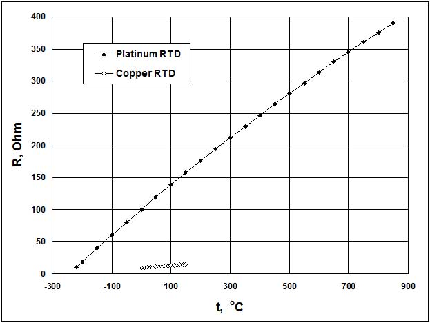
Figure 1: Resistance vs temperature for platinum and copper RTD.
Fig. 2 shows the assembly of RTDs. Sensitive elements of RTDs are made of a thin wire 1 with outside diameter equal to 0.025 mm (platinum RTD) and 0.1 mm (copper RTD) double wounded (non-inductive) on a micaceous or porcelain stem 2. For mechanical strength the sensitive element is placed in the ceramic insulator tube 3 filled by extremely fine granular powder; extension wires are placed in the ceramic insulator 4, and entire assembly is covered by a protective sheath of stainless steel 5. The space between the sheath and ceramic insulator is filled by ceramic packing powder 6. To avoid contact of sensitive element with environment, sensitive assembly is protected by high-temperature hermetic seal 7. The contact between the wire of the sensitive element and the ceramic encapsulation permits a rapid speed of response.
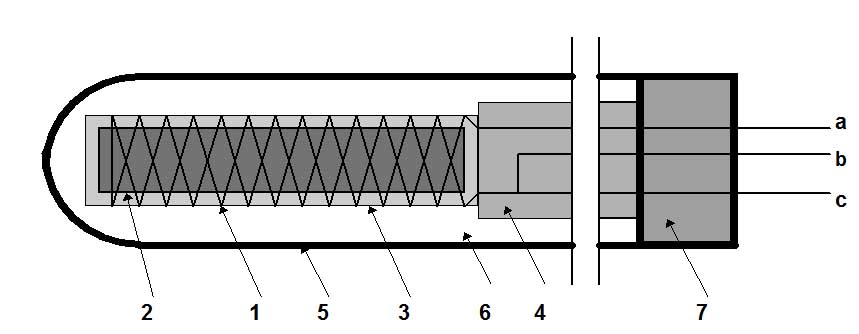
Figure 2: RTD assembly.
For measurements of resistance of RTDs several methods are used. Among them the most widely used is a method employing a Wheatstone bridge (Figure 3). In this case RTD is connected to the bridge by two connecting cables (conductors). The bridge is powered by direct current power supply in the points “a” and “b”. RTD is immersed in the media, which temperature to be measured. When this bridge is in balance, then there is no voltage between points “c” and “d”, and zero-indicator (ZI) shows no current.