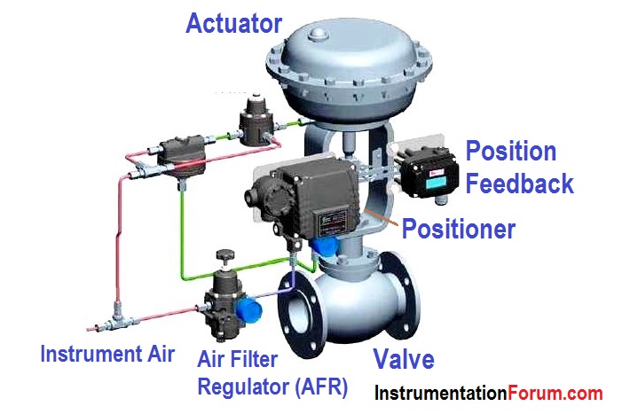
Control Valve is the term used for a valve that has the ability to throatling or too gradual changing. Is on-off valve including valve controlled? Yes, but rarely referred to as a control valve. Control valve in particular for the valve that can receive both analog commands with analog signals and digital signal collection.
Calibration control valve is needed to ensure that the control valve actuation can produce responses as desired by the control system in a process. Actuation response is meant to include the accuracy values, Linearity, and also the response time course.
Control valve as an actuator in a control loop has an important role in a process more regulating. Meregulating failure in a process abnormality is an indication of an ongoing process that if the shutdown effect.
There are 2 kinds of calibration commonly known in the valve control Manual and Auto Calibration Calibration.
Manual calibration is the calibration by using the manual input to control valve. The core of the calibration is to bring value to the actual value. Value of a control valve is opening / closing.
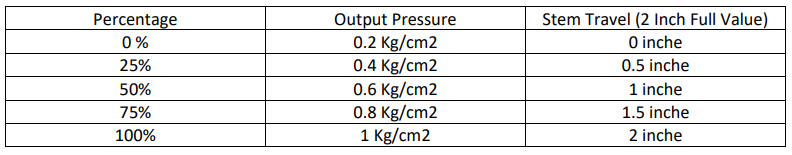
Openings in the form of a percentage value. Common sense says that the five points which is used as a benchmark standard for control valve opening. 0%, 25%, 50%, 75%, 100%.
Calibration activity is to mengsinkronkan valve control inputs in the form of analogue signal (assumed Hart) by opening control valve. Value as a standard 4-20 mA instrumentation expanded to represent the opening of a 4mA, 8mA, 12mA, 16mA, 20mA.
In the known control valve terminology Quick Opening, Linear, Equal Percentage. This term to indicate the relationship between the opening and flow rate. The question that arises is whether the Valve Quick Opening, or Equal Percentage travelnya the opening is not linear with input signal? Fisher people’s opinion that the Quick Opening, Linear, and Equal Percentage is already characteristik trim is set on the geometry of the valve Cv values. So that the input signal to the opening should always be linear.
But there again the question why it is possible to change the input to Quick Opening characteristik, Linear, and Equal Percentage with a setting of 375 Handheld Communicator Hart? For what?. To produce a response signal or a parabolic curve.
I have not found specific answers about it. But the requirement of the process allows to give a response that is parabolic of a control valve, when the process to be controlled is not linear. So that it can be concluded that the control response can also be a quick opening, linear, or equal percentage.
Distance travel is also important to note in the calibration. Distance travel is absolutely mechanical control adjusts the valve stem. Travel distance is the distance from fully open to fully closed. Fully closed means had not diadjust but to fully open the valve to give some flexibility to the user to shorten or lengthen travel.
The main reference in the construction phase is that the travel distance should be in accordance with the data sheet. If the distance of travel of the control valve will open as the maximum detect 100%.
Suppose you are a distance control valve travelnya 3 “, but in reality is mechanical is 4” then the travel value of the calibration phase 4 “is considered as 100%, when it should be when referring to the datasheet to travel 3” then the value of opening 4 "is approximately 133%.
Therefore have to be really sure that the travel distance is in compliance with the requirements in the datasheet to adjustment on the stem.
Autocalibration can be done by using Fisher 375 Handheld. Select the menu and auto calibration. Automatic valve for menstroke highest postition with full control valve, the value will be regarded as automatic 100% value. Then the valve will be fully closed for the value, and the value is 0%. Valve and calibrated already.
Initial opening becomes important when tight shut-off to be the main thing. This means that when fully closed valve, 0% controls have to be really tight. How sure? Case for FC, the first step make sure that when the feedback shows 0%, then its pressure release control valve, then there is no movement down again.
Or by sending a signal below the minimum value of 4 mA, 3.8 mA for example the control valve can also have not come down again. Kalo is calibrated control valve but when delivered 3.8 mA control signal valve is still down more then the value of 0% is not fully tight.
Things to note when doing the calibration is in the control valve out of service condition. Protection and calibration must be removed. Make sure the input characteristics and send to the control valve. After calibration is complete the control valve is returned to the condition of in-service.
There was a question from a blogger know about how the calibration by using PLCs from HMI. This term is known as Remote Calibration. In this project the remote calibration is generally performed in the Pre-Commissioning phase. In Hart & Fieldbus technology, remote calibration is normally done.
There is special software that serves as Communicator Hart & FF is installed in the HMI that can run the calibration mode. AMS Device Manager software I’ve ever used clay for the remote control valve calibration. Without additional software but want to do calibration? Hmm … I’ve found a PLC belom could do without the help of remote calibration technician in the field. It means I never know the PLC can mengedjust I / P is automatic if there is a problem when the signal is sent 25% (8 mA) was 50% valvenya openings.
Another story, if such condition would then be sent technicians to the field to ngedjust I / P, because if the case is adjustmentnya by technicians who do not PLC calibration but the technician who did the calibration. PLC works there only send signal AO.
Does AO dr PLC for opening a percentage as well? Mmm … that’s PLCs can be defined through the program. Want contrived percentage or other amount that can be done by programmers.
But normally the output logic PID algorithm calculation is set in the form of MV and this percentage is the control command, is also opening the valve unit is the percentage the command signal from the PLC output (input to control valve) are also more fit in the form of percentage.
Air to Close - Air to Open / Fail to Open - Fail to Close
There is enough explanation easy to understand from a senior one kumpeni in Jakarta about the concept of FOs / FC this. The main principle used for determining the FC / FO a Control Valve is when the files on the system control valve is in safe condition (low energy).
Low energy of a system must be defined by a team of multi-disciplinary involving mainly disciplinary process. Reasonnya play when there is failure then the system should not overpressure, over the level, over flow etc., but getting the energy to decrease and decrease.
Proverbial you have a control valve on the inlet pipe which regulates fluid into the vessel, so if there is fail then you’ll want to stop the flow so as not to overflow the control valve, attach the Fail to Close (Air to Open).
Example for Fail to Open (Air to Close) is the easiest for overpressure protection of a vessel. If the pressure is too high then there must be a discarded gas. If for example the line exhaust valve control is given to Fail to Open, which means that if the system fails then the control valve to be open and protect the pressure of the overpressure in the vessel.
More exactly must use the evaluation process the expert is a process engineer. The key is in the valve control conditions fail, then the system should lead not to OVER SECURE.
Author - Nova Kurniawan