A Controller Area Network (CAN bus) is a robust vehicle bus standard designed to allow microcontrollers and devices to communicate with each other in applications without a host computer. It is a message-based protocol, designed originally for multiplex electrical wiring within automobiles to save on copper, but is also used in many other contexts.
CAN is a multi-master serial bus standard for connecting Electronic Control Units [ECUs] also known as nodes. Two or more nodes are required on the CAN network to communicate. The complexity of the node can range from a simple I/O device up to an embedded computer with a CAN interface and sophisticated software. The node may also be a gateway allowing a standard computer to communicate over a USB or Ethernet port to the devices on a CAN network.
All nodes are connected to each other through a two wire bus. The wires are a twisted pair with a 120 Ω (nominal) characteristic impedance.
ISO 11898-2, also called high speed CAN, uses a linear bus terminated at each end with 120 Ω resistors.
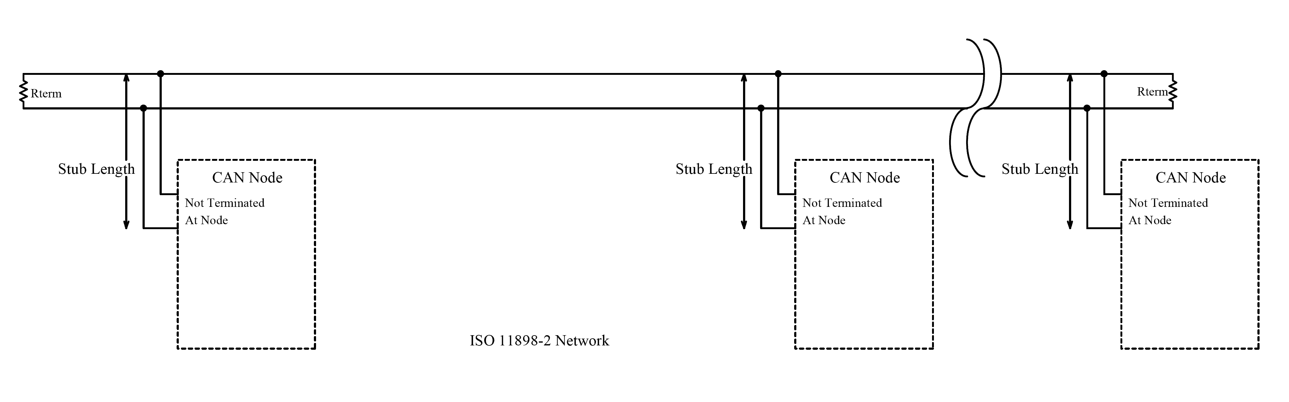
Fig : High Speed CAN Network. ISO 11898-2
High speed CAN signaling drives the CAN high wire towards 5 V and the CAN low wire towards 0 V when transmitting a dominant (0), and does not drive either wire when transmitting a recessive (1). The dominant differential voltage is a nominal 2 V. The termination resistor passively returns the two wires to a nominal differential voltage of 0 V. The dominant common mode voltage must be within 1.5 to 3.5 V of common and the recessive common mode voltage must be within +/-12 of common.
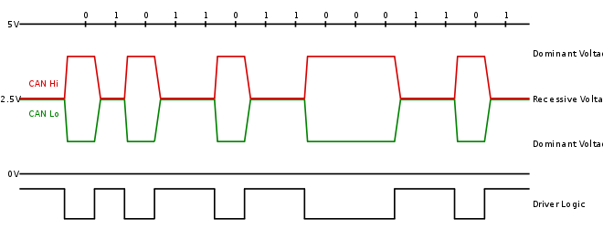
Fig : High Speed CAN Signaling. ISO 11898-2
ISO 11898-3, also called low speed or fault tolerant CAN, uses a linear bus, star bus or multiple star buses connected by a linear bus and is terminated at each node by a fraction of the overall termination resistance. The overall termination resistance should be about 100 Ω, but not less than 100 Ω.
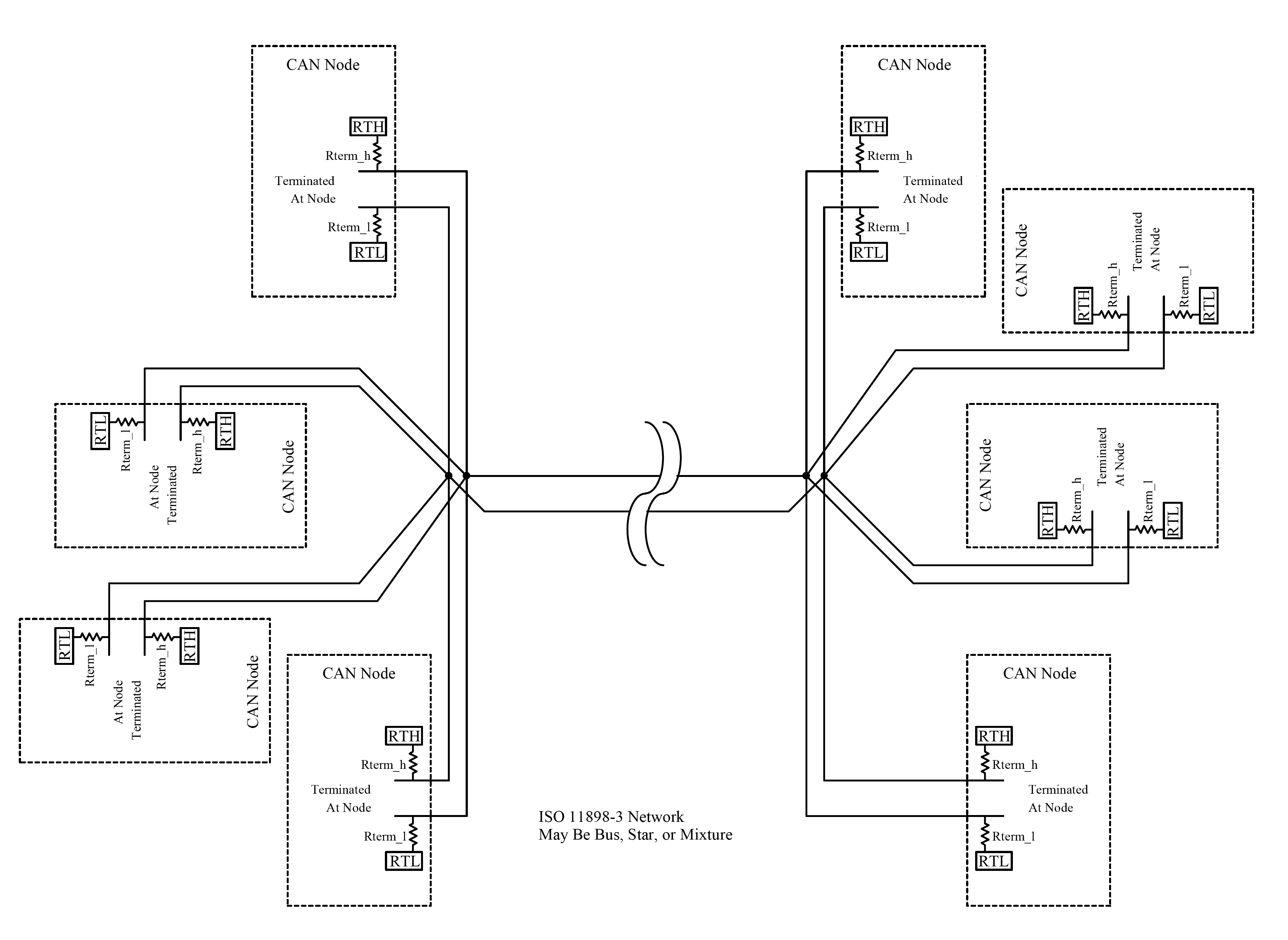
Fig : Low Speed Fault Tolerant CAN Network. ISO 11898-3
Low speed/Fault tolerant CAN signaling drives the CAN high wire towards 5 V and the CAN low wire towards 0 V when transmitting a dominant (0), and does not drive either wire when transmitting a recessive (1). The dominant differential voltage must be greater than 2.3 V (with a 5 V Vcc) and the recessive differential voltage must be less than 0.6 V The termination resistors passively return the CAN low wire to RTH where RTH is a minimum of 4.7 V (Vcc - 0.3 V where Vcc is 5 V nominal) and the CAN high wire to RTL where RTL is a maximum of 0.3 V. Both wires must be able to handle -27 to 40 V without damage.
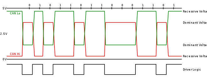
Fig : Low Speed CAN Signaling. ISO 11898-3
With both high speed and low speed CAN, the speed of the transition is faster when a recessive to dominant transition occurs since the CAN wires are being actively driven. The speed of the dominant to recessive transition depends primarily on the length of the CAN network and the capacitance of the wire used.
High speed CAN is usually used in automotive and industrial applications where the bus runs from one end of the environment to the other. Fault tolerant CAN is often used where groups of nodes need to be connected together.
The ISO specifications require the bus be kept within a minimum and maximum common mode bus voltage, but do not define how to keep the bus within this range.
The CAN bus must be terminated. The termination resistors are needed to suppress reflections as well as return the bus to its recessive or idle state.
High speed CAN uses a 120 Ω resistor at each end of a linear bus. Low speed CAN uses resistors at each node. Other types of terminations may be used such as the Terminating Bias Circuit defined in ISO11783 [8]
A terminating bias circuit provides power and ground in addition to the CAN signaling on a four-wire cable. This provides automatic electrical bias and termination at each end of each bus segment. An ISO11783 network is designed for hot plug-in and removal of bus segments and ECUs.
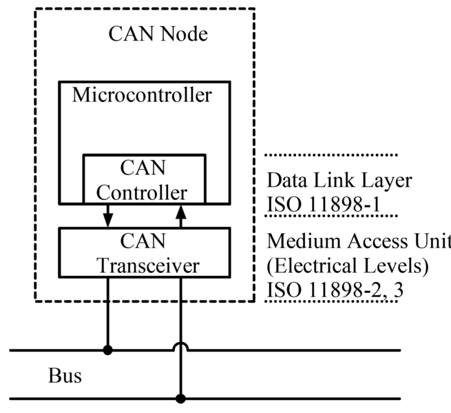
Fig : CANbus Node
Each node requires a:
- Central processing unit, microprocessor, or host processor
- The host processor decides what the received messages mean and what messages it wants to transmit.
- Sensors, actuators and control devices can be connected to the host processor.
- CAN controller; often an integral part of the microcontroller
- Receiving: the CAN controller stores the received serial bits from the bus until an entire message is available, which can then be fetched by the host processor (usually by the CAN controller triggering an interrupt).
- Sending: the host processor sends the transmit message(s) to a CAN controller, which transmits the bits serially onto the bus when the bus is free.
- Transceiver Defined by ISO 11898-2/3 Medium Access Unit [MAU] standards
- Receiving: it converts the data stream from CANbus levels to levels that the CAN controller uses. It usually has protective circuitry to protect the CAN controller.
- Transmitting: it converts the data stream from the CAN controller to CANbus levels.
Each node is able to send and receive messages, but not simultaneously. A message or Frame consists primarily of the ID (identifier), which represents the priority of the message, and up to eight data bytes. A CRC, acknowledge slot [ACK] and other overhead are also part of the message. The improved CAN FD extends the length of the data section to up to 64 bytes per frame. The message is transmitted serially onto the bus using a non-return-to-zero (NRZ) format and may be received by all nodes.
The devices that are connected by a CAN network are typically sensors, actuators, and other control devices. These devices are connected to the bus through a host processor, a CAN controller, and a CAN transceiver.
Data transmission
CAN data transmission uses a lossless bitwise arbitration method of contention resolution. This arbitration method requires all nodes on the CAN network to be synchronized to sample every bit on the CAN network at the same time. This is why some call CAN synchronous. Unfortunately the term synchronous is imprecise since the data is transmitted without a clock signal in an asynchronous format.
The CAN specifications use the terms “dominant” bits and “recessive” bits where dominant is a logical 0 (actively driven to a voltage by the transmitter) and recessive is a logical 1 (passively returned to a voltage by a resistor). The idle state is represented by the recessive level (Logical 1). If one node transmits a dominant bit and another node transmits a recessive bit then there is a collision and the dominant bit “wins”. This means there is no delay to the higher-priority message, and the node transmitting the lower priority message automatically attempts to re-transmit six bit clocks after the end of the dominant message. This makes CAN very suitable as a real time prioritized communications system.
The exact voltages for a logical 0 or 1 depend on the physical layer used, but the basic principle of CAN requires that each node listens to the data on the CAN network including the transmitting node(s) itself (themselves). If a logical 1 is transmitted by all transmitting nodes at the same time, then a logical 1 is seen by all of the nodes, including both the transmitting node(s) and receiving node(s). If a logical 0 is transmitted by all transmitting node(s) at the same time, then a logical 0 is seen by all nodes. If a logical 0 is being transmitted by one or more nodes, and a logical 1 is being transmitted by one or more nodes, then a logical 0 is seen by all nodes including the node(s) transmitting the logical 1.
When a node transmits a logical 1 but sees a logical 0, it realizes that there is a contention and it quits transmitting. By using this process, any node that transmits a logical 1 when another node transmits a logical 0 “drops out” or loses the arbitration. A node that loses arbitration re-queues its message for later transmission and the CAN frame bit-stream continues without error until only one node is left transmitting. This means that the node that transmits the first 1 loses arbitration. Since the 11 (or 29 for CAN 2.0B) bit identifier is transmitted by all nodes at the start of the CAN frame, the node with the lowest identifier transmits more zeros at the start of the frame, and that is the node that wins the arbitration or has the highest priority.
ID allocation
Message IDs must be unique on a single CAN bus, otherwise two nodes would continue transmission beyond the end of the arbitration field (ID) causing an error.
In the early 1990s, the choice of IDs for messages was done simply on the basis of identifying the type of data and the sending node; however, as the ID is also used as the message priority, this led to poor real-time performance. In those scenarios, a low CAN bus utilization of circa 30% was commonly required to ensure that all messages would meet their deadlines. However, if IDs are instead determined based on the deadline of the message, the lower the numerical ID and hence the higher the message priority, then bus utilizations of 70 to 80% can typically be achieved before any message deadlines are missed.