A Piping and Instrumentation Diagram (P&ID) is the most common method of illustrating the functional relationship of piping, valves (automated and manual), pipe sizes, sample points and instrumentation.
A moderate level of mechanical detail is provided for process equipment, so that the piping and instrumentation can be precisely documented. International symbol standards are used for piping, equipment and instruments (ISA, 1992).
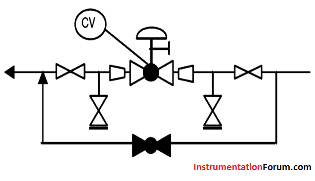
A typical arrangement used to represent control valves on P&ID is depicted below.
Control Valves in Process Drawings
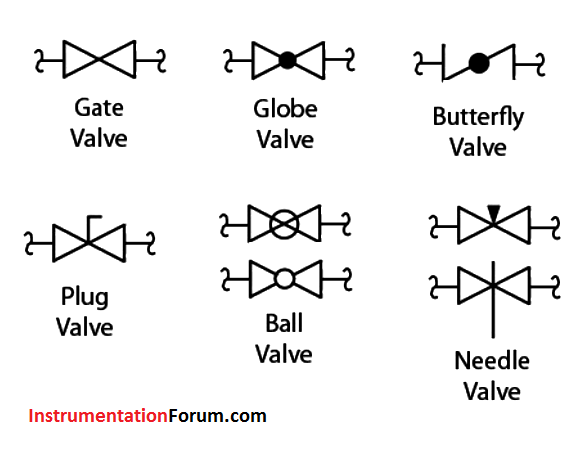
The figure below shows a list of typical valve symbols used in industry.
Control Valves P&ID Symbols
Control valves may fail in various positions: open, closed, locked, or indeterminate, and it needs to be shown on the P&ID.
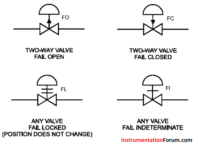
The fail positions may be identified using letters below the valve symbol: FO for Fail Open; FC for Fail Closed; FL for Fail Last or Locked; and FI for Fail Indeterminate.
The fail positions may also be identified by an arrow. An arrow up signifies the valve fail open and an arrow down is fail close. A crossing line is fail indeterminate.
Two crossing lines indicate fail locked or last position.