Damaged Transmitter Siemens

Hi Guyss;

Now i am working on Siemens Distributor as technical support.
I want asking you about damaged transmitter.

I’ve faced 2 different repots from customers.

Case 1:

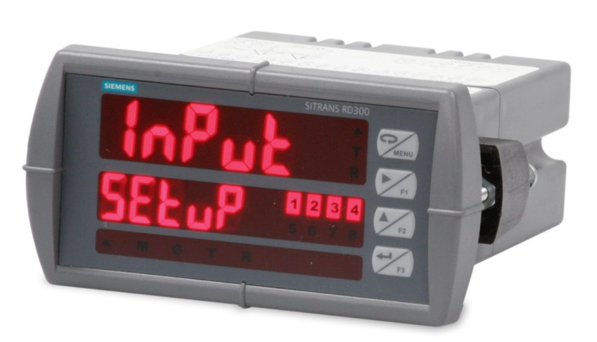
Customers reported their pressure transmitter P320 is totally off. Then I looped remote display RD300 to find out the current looping on transmitter.

I set the lower scale: 4mA = 4, and the upper scale: 20mA = 20. The aim of my looping is to find out the loop current at the transmitter.

Then after I turn on the rd300, the transmitter’s display remains off and the loop current reads 3.39 mA (less than 4mA) and the display remains off. It’s in the first picture.

Then, the final decision from Siemens that damage occured on the display. After the new display arrived and I changed the new display to the transmitter, it still doesn’t turn on and the current remains 3.4 mA.

Case 2:

Customers report that their probe LU level transmitter is completely off. Even DCS does not receive a signal from the transmitter.

Then I did the same thing with current looping using RD 300. I set the lower scale: 4mA = 4, and the upper scale: 20mA = 20.

Then after I turned on the RD 300, it displayed the number 999.9 mA (more than 20 mA). But the transmitter screen is on but displays showed strange symbol.

Here is my assumption that the transmitter has shorted circuit because the current is approaching infinite.

But the transmitter still doesn’t work after I try to make a move, the screen display doesn’t change.

My question is, what difference does it make if the looping current reads less than 4mA or more than 20 mA. Both of my observations make the transmitter turn off, but what kind of damage was caused?

Thank you, sorry if my question is too long.

@frankyphs what is the need of loop indicator? you can simply connect a hart communicator or a multimeter to read the values?

Hi Vignesh,

I dont have hart communicator. And why i did looping using loop indicator, because this RD 300 is the simplest device that i have to replace the load (in 2 wire looping). Why did i dont use multimeter? I dont have 250 ohm, as simply as that. I have used remote display (RD300) many times and i sure that this device is accurate. I just want asking about the explanation of the current out of the range (<4 mA and > 20mA). What if you find that your transmitter have 999,9 mA on your current looping transmitter? What is your diagnose? Thank you.

@frankyphs I think you need to connect a load resistor also with loop power indicator.

If you install the loop indicator in the field then we have

transmitter + Loop Indicator + Load Resistor in Control Room.

Hi Santosh…

You can find Siemens RD300 manual on internet. In electrical connection part, siemens clearly says that you don’t need any additional resistor. The function of RD same as PLC/any controller, to replace the 250ohm resistance in looping 2 wire. I have used RD300 many times, it always show same as transmitter show on display (only when you do the right scaling span). Not only show the transmitter display (ex : how much the level, the pressure, the flow), rd300 always can show the ampere (4 set to 4, 20 set to 20) and this why I did. My question still the same ; how if you find current reading on your 2 wire is 999,9 mA? Example you find the 999,9 mA on transmitter with the right way you consider. What’s your diagnose? Thank you.

@frankyphs

Case 1:

The loop current purely depends on transmitter configuration and measured process variable. We don’t know what must be the loop current without reading the transmitter display or by connecting a HART communicator.

The testing with loop indicator is not the correct procedure without knowing the loop current. The transmitter loop current may be of any value, it may be as per the measured process variable (PV) or may not be if there is some problem with circuit or with configuration/calibration.

First, check the transmitter configuration, check measured PV and its equivalent loop current (with HART) then you can use loop indicator for verification purposes or a mulitmeter.

You can only verify with loop power indicator when you know the transmitter loop current.

Say, for Flow transmitter (FT) when flow is zero, the expected loop current is 4 mA but due to some problem with configuration or D/A trim settings the FT providing 3.5 mA then it is not possible to use a loop power indicator for testing or verifying the loop current as transmitter itself generating this loop current as per its present settings.

You can do a factory reset to remove all the changes done on the transmitter.

Case 2:

I don’t think loop indicators support to display a current of 999.9 mA as generally they are available in standard measurement ranges like 4 to 20 mA or 0 to 20 mA.

Check your setup or connections. Also refer loop indicator manual → troubelshooting tips.

As discussed above, we need to check the transmitter configuration, read the transmitter PV and analog current output with HART, then only we can use a loop indicator for verification purposes.

Sometimes Loop indicator or multimeter is not enough to carry out the troubleshooting activities. You need a HART communicator or relevant device to read/write the transmitter parameters.

Hii @Bharadwaj ,

For my testing procedure that i’ve used, i sure that it accurate and effective. Some example are below :

  1. I have tested RD300 loop with P320 siemens (i set the span for transmitter is 0-1600 mbar). So i set the scaling in RD 300 : lower scale (4 mA = 0) and upper scale (20 mA = 1,6 bar ) same as transmitter’s span.
    I tried to see the similarity between what the transmitter’s display show and RD300’s show, and testing for check current looping (4mA set to 4, and 20mA set to 20).
    And this is what i got : In the beginning, the transmitter show 0.000 bar and the current read as 3,9xx mA. I start to blow up the pipe using my mouth, and the pressure start to raise up. Suddenly i use my hand to close the pipe to maintaine the value of pressure. The transmitter show the pressure value being 0,7 bar. The current looping also raise linearly with the pressure value, it show 11,xx mA in RD 300. When i check for pressure value, the RD300 show the same value as transmitter show (small delay just because transmitter have response rate).

  2. I have looping RD300 using Siemens Radar LR250. I set Low calibration : 4 meter, and High Calibration : 0,5 meter. I set radar using level mode measurement (not space or distance). I set RD 300 scaling for check the similarity display between radar and RD300 and i set scaling to know current looping same as way as Pressure. I make a move on radar (i make observation on my office) and radar show the level is 2 meter. I see the RD 300 show as the same , 2 meter. Then i change span of RD 300 to know the current looping, it show 12 mA (LINEAR).

Because of this 2 experiment, i always feel confident to bring this device to test all the reported transmitter. I also read on some source of instrument forum, the instrument’s company do not imppressed to sell the small part of transmitter. So when they face the damaged transmitter report from customer, as long as customer still have the warranty, they just send new transmitter to customer. Some expert think that the transmitter problem so complex, so just claim the new one when you still have the warranty.

But there is the expert give me the possibility cause of damaged transmitter :

  • heat kills electronic components and seals. Over heating any electronic device shortens its life considerably.
  • over pressuring pressure components either kills the sensor or distorts so badly that the readings are meaningless.
  • water or liquid intrusion into electronic compartments causes damage
  • near lightning strikes damage electronics
  • excessive common mode voltage can burn out electronics
  • corrosion causes electrical connection problems which causes faults.
  • Applying 24Vdc across the input resistor of 4-20mA input channel will burn out the little 1/8W resistor (when someone puts a jumper across the (+) and (-) terminals of a powered, 2 wire transmitter)
  • dirt and grit in the flow stream of a turbine meter
  • customers will connect 120Vac across the terminals 24Vdc device and burn it up.

But for the difference between <4 mA and >20 mA, i still dont get the explanation.

Thank you.

1 Like

Hi,

Agreed, thanks for sharing the detailed analysis and your experience with us.

Yes, you can use any related electronic device for testing purposes.

We can also use a simple multimeter to measure the loop current and convert it into measured Process variable (flow, level, pressure, etc) using a formula or use a loop power indicator, as per our convenience and experience.

But definitely we may be in need of HART communicator sometimes for configuration of transmitter. (purely depends on the type of problem)

Every problem will be unique and we may need different thinking and approach.

As discussed above, try to do factory reset and check the transmitter again.

We have many reasons, but with factory reset all the previous settings & configurations will be removed and it may solve the issue.

If the transmitter D/A trim are changed (measurement will be right but produces different current output) then the current may vary (one of the possibility) or a problem with D/A circuit, or any other one. With these problems loop indicator/multimeters will not help us.

In this case, use measured process variable, LRV & URV of transmitter range and then calculate the loop current output (4-20 mA) and cross-check with transmitter loop current).

Note: Sometimes the transmitter will display correct loop current in HART but may generate different loop current at output if there is a problem with D/A circuit. So check loop current in HART and also measure with multimeter/loop-indicator.

1 Like