Delta modulation(DM) is process of modulation in which train of fixed width pulses is transmitted. Their polarity indicates whether the demodulator output should rise or fall at each pulse. The input is caused to rise or fall by a fixed step height at each pulse. Figure 18.20 shows the block diagram of a DM system.
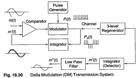
In the DM system, the modulating signal m(t) is applied to the non inverting input of a high gain differential comparator. A reconstructed signal version of this signal, m’(t), is applied to the inverting input. The difference comparator is in saturation, either positive or negative, depending on the polarity of the difference voltage between the input signals. Hence, the output is ± 1.
The modulator receives a train of unipolar pulses [Pi(t)] recurring at the desired sampling rate and either transmits directly for (a + 1) inputs or inverts their polarity for (a — 1) inputs. This signal is transmitted as the output signal [P0(t)] and is also passed to a local integrating circuit. This integrator causes m’(t) to rise or fall by a fixed step height for each positive and negative pulse applied to its input. The height of the pulse can be adjusted by changing the gain factor of the integrator. An increase causes the step waveform to have a higher maximum rate of rise (Rmax).
At the receiver, a regenerator reshapes the received signal and removes most of the noise. The signal is then fed to another integrator which reconstructs m’(t), the step waveform. This is then passed through a low pass filter to remove the quantization noise, leaving a replica m”(t) of the original signal.
Delta modulation is less frequently used than PWM and PCM. Currently, it is being applied to satellite communications, TV and subscriber telephone loops. It is less complex and therefore less costly than PCM, more tolerant to transmission errors and does not need the synchronization requirements of PCM. On the other hand, it is sensitive to slope overload and is unsuitable for timesharing as an encoder/decoder among multiple channels.
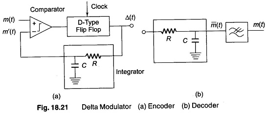
The delta modulator transmits binary output pulses whose polarity depends upon the difference between the modulating signal and the feedback signal corresponding to the history of the signals previously sent. In the simple DM of Fig. 18.21, the integrated feedback m’(t) is compared to the input signal m(t). If m(t) > m’(t), a positive pulse forms the output Δt, and if m(t) < m’(t), a negative pulse forms the transmitted signal. This output pulse train also forms the approximation m’(t), after being integrated.
The following waveform sketches will clarify the operation of this modulator. As illustrated in Fig. 18.22, a series of triangular waveform results for m’(t) when there is no signal applied to the delta modulator. This is because integration of a constant gives a ramp. In this idling condition, the transmitted signal consists of alternate positive and negative pulses. The difference between the original signal, m(t) and the reconstructed signal m’(t), result in an error signal, which is often called granular or quantization noise. This noise can be decreased by either decreasing the magnitude of the step size a or by increasing the sampling frequency.
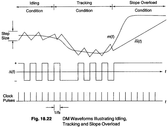
If m(t) exceeds the feedback signal m’(t), the transmitted wave train remains positive. When m’(t) begins to overshoot m(t), the encoder output begins transmitting negative pulses. If the modulating signal changes more rapidly than the encoder can follow, slope overload occurs. This slope overload, shown towards the right of Fig. 18.22, causes waveform distortion and is one of the severe limitations of DM. The integrator is unable to closely track large amplitude, high frequency signals.
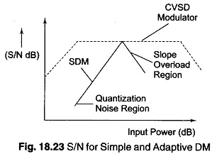
The difference between m’(t) and m(t) in slope overload is called the slope overload noise. This noise greatly exceeds quantization noise. The S/N ratio, as a function of input signal power, initially increases with signal power until slope overload is reached as illustrated in Fig. 18.23. This increase is due to the signal power term increasing while the co-term, chiefly quantization noise, remains fixed. Upon a further increase in signal power, slope overload occurs and the S/N ratio suffers.
Companded Delta Modulation
Studying the S/N response of the simple DM scheme shown in Fig. 18.23, shows that the S/N ratio varies considerably with signal power. At low signal power, the S/N ratio is much worse than at high signal power, as long as the signal remains within the quantization noise region.
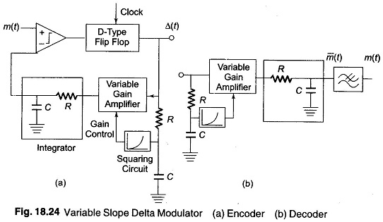
In order to maintain a more constant S/N ratio, the step size is made adaptable to the input signal amplitude. For small inputs m(t), the step size is kept small, and increased as the input signal is increased. This makes the noise power vary with signal power, maintaining a constant S/N ratio over a fairly large range of input power levels. In addition, slope overload is less likely to occur since the step size are the largest when nearing the region of constant S/N ratio.
For telephony, the type of adaptive delta modulation used is a continuous variable slope DM (CVSD). A block diagram of such a modulator is shown in Fig. 18.24. The squaring circuit causes the gain of the feedback amplifier to increase with increase in signal amplitude, regardless of the polarity of the voltage. In addition, by squaring the quantization noise, power is made to vary linearly with input signal variations.