This articles shares information on how to Download PLC Ladder Logic with RSLogix500 plc programming software.
STEP 1 - Connect the hardware
The type cable you use to connect your PC and PLC depends upon the PLC hardware installed. If you have have a serial connection on your PLC controller module you will use an RS-232 cable. However, some PLC installations at SLAC also have an ethernet module (eg ENET), in which case an Ethernet connection can be setup. Follow the directions below that apply to your installation.
RS-232 connection
Connect a null-modem 9-pin cable from your PC to the serial port on the PLC. This is the most common way to program a PLC in the field. The Allen-Bradley part no. for this cable is 1756-CP3/A.
Ethernet connection
If using Ethernet, you can connect a crossover cable from your PC to the Ethernet Module. To do this, your PC and PLC must be on the same subnet.
If the PLC is on an accessible network, you can connect your PC to that network.
STEP 2 - Open RSLinx and bring up the list of communication drivers
Open RSLINX.
If you have already setup a communications driver before, skip to STEP 5 .
Click on Communications and Configure Driver.
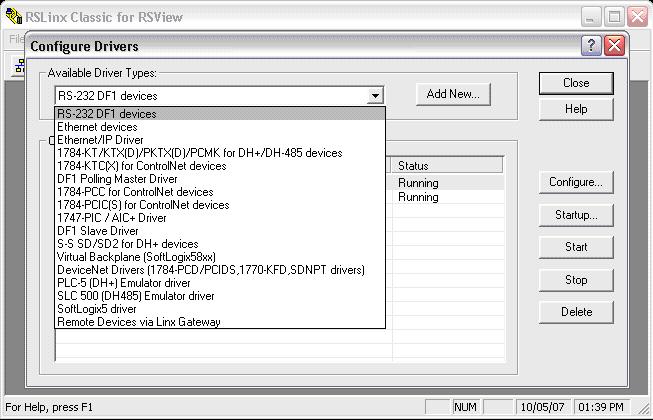
STEP 3 - Add a new communications driver
Click on the drop-down menu and select RS-232 DF1 devices.
Click on Add New.
A window will pop up. Just click OK.
For an Ethernet connection, click on Ethernet/IP Driver .
This will browse the local subnet or remote subnet for PLC devices.
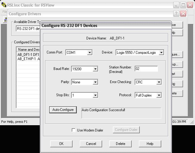
STEP 4 - Configure the communications driver
A window will come up to configure the communication.
Just click on Auto-Configure.
For an Ethernet connection, choose whether you want to browse a local or remote subnet. A local subnet will be used for most cases.
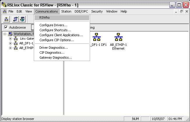
STEP 5 - Display the communication drivers
Click on Communications and RSWho.
This shows the communication drivers you have setup.
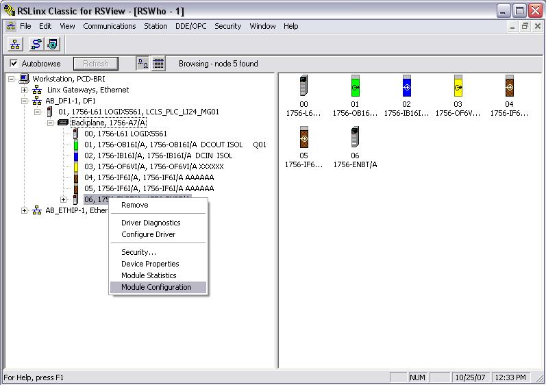
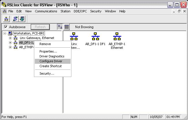
STEP 6 - Reconfigure a communications driver
This step is for users who have setup communications before and need to make a change.
You can right click on the communications driver and click Configure Driver.
This brings up the window from STEP 5 , where you can change the configuration.
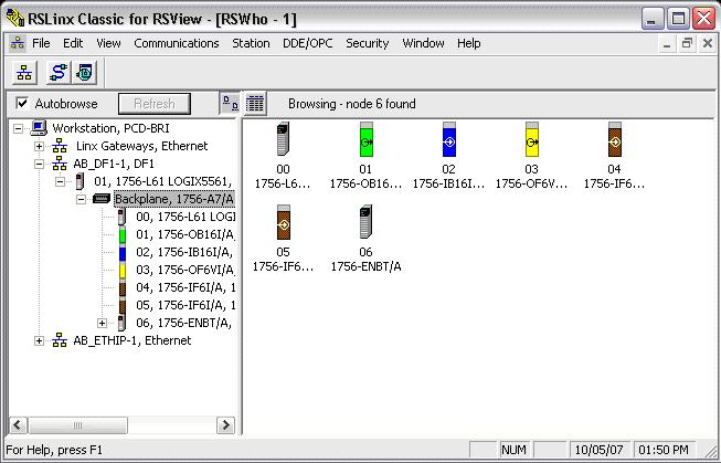
STEP 7 - Display attached devices
If you expand the icons by clicking on the + symbol, you should see your device.
If using Ethernet, you will see all PLC devices in your subnet.
PART II: Download the Ladder Logic to your PLC
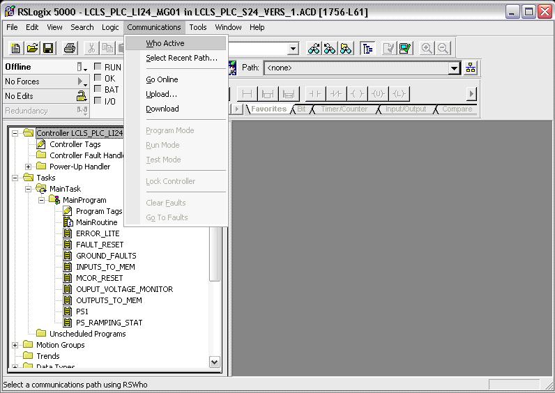
STEP 8 - Open RSLogix5000
Open RSLogix5000 and the applicable file to download.
Click Communications and Who Active.
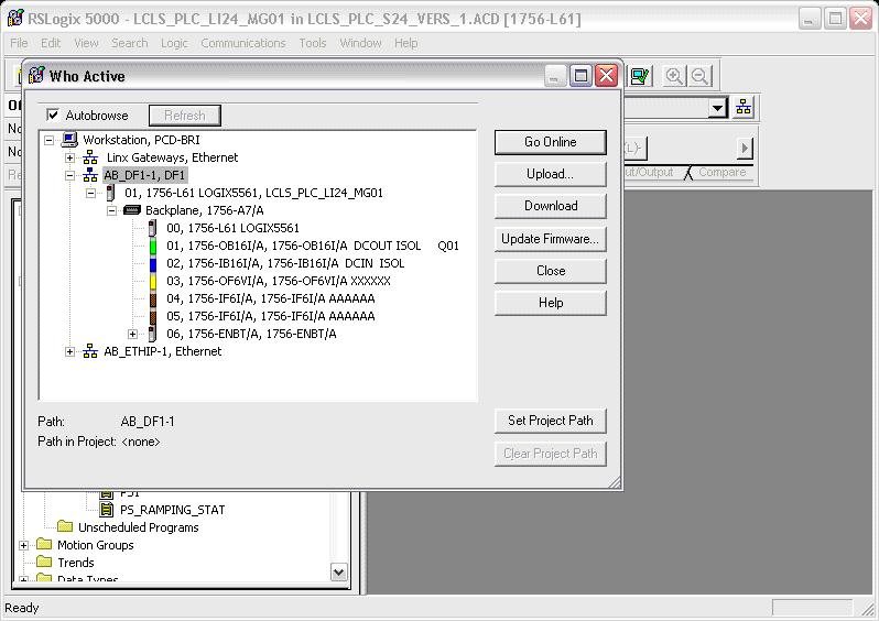
STEP 9 - Download program
''Warning: This step will take your PLC out of Run mode."
Ensure that the PLC keyswitch in the REM or PROG position.
Click on the + next to your communications driver until you find your PLC.
Click Download and Download again on the new pop up window.
You also have the option to Go Online in this window.
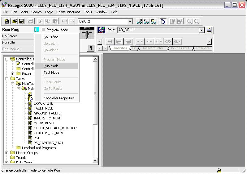
STEP 10 - Place PLC in Run mode
Note - Most PLCs are equipped with nonvolatile memory. Proceed to STEP 11 to load the program into nonvolatile memory. Otherwise, proceed with the next steps to place the PLC in Run mode.
There are two methods of placing the PLC in Run mode; Run and Remote Run. Each has its advantages and disadvantages.
RUN: This is done by simply placing the keyswitch in the RUN position. In this mode, the PLC cannot be programmed remotely. This will prevent someone from “accidentally” taking the PLC out of Run mode or modifying the Ladder Logic. In this mode, the PLC will NOT load the Ladder Logic stored in nonvolatile memory during power up.
REMOTE RUN: This is done by placing the keyswitch in the REM position and going online to tell the PLC to go into Run mode. In this mode, the PLC can be programmed remotely, whether intentional or unintentional. It is only in this mode that the PLC is able to load the Ladder Logic in nonvolatile memory during power up.
To place the PLC in REMOTE RUN:
Place the PLC keyswitch in the REM position.
Go online with the PLC. Refer to the previous step if you need help.
Click on the small PLC icon and again on Run Mode.
PART III: Load Ladder Logic to Nonvolatile Memory
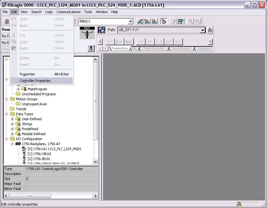
STEP 11 - Open Controller Properties window
When power is down for extended periods of time and the battery dies, the ladder logic loaded in the PLC disappears. Loading an image to nonvolatile memory ensures that the PLC loads the ladder logic from memory during power up.
Start by going online with the PLC and place it in PROG mode. Refer to STEP 9 to see a screen shot of the window with the Go Online option.
Click on the Edit menu and again on Controller Properties
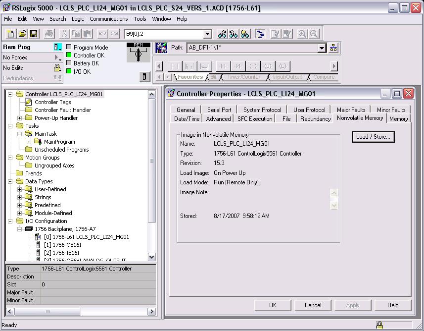
STEP 12 - Display the Nonvolatile Memory properties
A window will pop up displaying the controller properties.
Click on the Nonvolatile Memory tab.
Here you will see the image currently stored in nonvolatile memory.
Click on the Load/Store button.
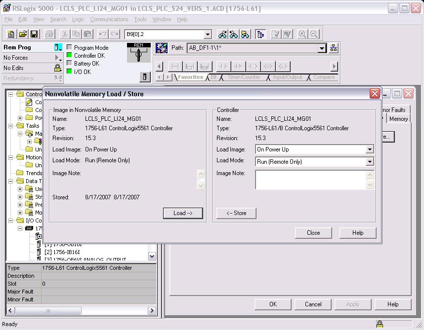
STEP 13 - Store program in nonvolatile memory
A window will pop up with information on the image in memory and options to Load or Store an image.
Select options: Load Image: On Power Up and Load Mode: Run (Remote Only).
Click on <-- Store.
Two windows will pop up. Click on Yes and OK.
STEP 14 - Go back online and into Run mode
You should have now successfully downloaded the program into the PLC and stored it in nonvolatile memory.
The final step is to go back online with the PLC and place it in RUN mode.
Refer to STEP 9 and STEP 10 for instructions.