Distributed Control Systems (DCS) is an essential part of all modern day industries and is a complex computer based industrial monitoring and control system of industrial processes.
This article provides an overview of the distributed control systems and takes readers to the highest levels of operations of DCS in subsequent chapters.
Distributed Control Systems Learning objectives
In this chapter we will learn the following:
-
Introduction
-
Basic concepts of distributed computing
-
Evolution of distributed computing system
-
Present market trends in DCS
-
Basic DCS specification
-
General description of a commercial DCS
-
Advantage of DCS system
-
DCS selection criteria
-
DCS architecture
-
DCS configuration
-
Conclusion
2.1 Introduction
The concept of automatic control of a process require two major operations to be accomplished; the transmission of signals i.e., information flow back and forth the process and the manipulation of control actions (decision making) on the process to achieve results.
Carrying out these operations in an actual process plant requires a set of hardware and instrumentation that serve as the platform for these tasks. Distributed control system (DCS) is one such control platform. It may be termed as the infrastructure for all control strategies starting from the lowliest to advanced control systems
Over the years, due to continuous technological innovations, the functional aspects of DCS have changed quite substantially. DCS was originally conceived as a replacement for large panels, located in central control rooms and containing a large number of process instruments.
The information flow and decision making role of the DCS quickly expanded. Some of the features added to the present day DCS systems include:
-
Advanced control functions, such as model reference control and expert systems
-
Information-analysis tools, such as statistical process control and intelligent alarming
-
Decision support applications such as predictive maintenance and document management system and
-
Business system integration capabilities.
Figure 2.1 below is the schematics of a basic Distributed Control System (DCS); the actual systems are based around this concept.

Figure 2.1
The schematics of a Basic Distributed Control System (DCS)
The present day DCS may be termed as the real-time component of a manufacturing facility’s enterprise management and control system (ERP), which virtually takes care of every aspect of the operation and management of both continuous and batch processes
2.2 Basic concepts of Distributed Computing
Conceptually, DCS has three essential qualities:
-
Distribute (process functions into smaller sub systems)
-
Compute (for automating the process) and set up a
-
System (to make it appear as an integrated system of process monitoring and control)
In DCS, the process plant’s monitoring and control functions are distributed into relatively small sets of semi-autonomous subsystems. These subsystems are interconnected via a high-speed communications network.
These functions include data collection, process control, presentation of information, process analysis and supervision, storage and retrieval of archived information, and the presentation and reporting of information.
Some of the advantages of distribution of functions over the conventional process monitoring and control system include:
a. lower exposure to component or subsystem failure
b. better isolation to facilitate maintenance
c. improved modularity for application development with geographical distribution leading to reduces installation costs and
d. more localized operational supervision while offering global access to information and control capabilities
The control function of DCS automates the manufacturing process; it integrates advanced regulatory control, logic and sequential control, and use of procedural languages into a unified application. These applications are capable of integrating with advanced application packages like Batch process control and Expert Systems.
The control aspect of the modern DCS has been further expanded to include functions that support manufacturing enterprise applications including:
a. Activity-based cost accounting
b. Production scheduling and dispatching
c. Preventative or predictive maintenance scheduling
d. HR functions like validation of employee job certification and readiness
e. Information exchange with business, logistics, and transportation applications
The systems aspect of a DCS organizes the command structure and information flow among its constituent parts including
a. Process signal input, signal conditioning
b. Process actuator signal output
c. Regulatory, combinatorial, and sequence logic operations and procedural and supervisory control
d. Human readable process displays of physical parameters, alarms, trends, and interpretation
e. Provide facilities for set point changes, manual overrides and alarm handling
f. Application subsystems such as process optimization and computer aided manufacturing
g. Information-storage subsystems for data archiving, data mining
h. Communications subsystems
2.3 Evolution of Distributed Computing System
DCS were originally designed to satisfy the needs of continuous processes. The controllers were based around the PID control algorithm such as summers, multipliers, selectors etc. The earlier DCS did not do a good job of addressing the requirement of discrete and batch control applications.
Since batch process typically needed regulatory, sequential and discrete type of controls, other equipment was needed to fill this void like the programmable logic controllers (PLCs).
Today’s DCS has evolved into a flexible and powerful integrated control system that supplies data acquisition, advanced process control and batch control capabilities
The consolidated approach to modern day controls started during 1940s ingenious mechanical and pneumatic devices controlled processes. These controls, which were normally located next to the process, had limited scope of controlling single or at best a few process conditions, such as temperature, pressure, or flow.
There were scarcity of means and ways to design and maintain coordinated process unit control systems. Processes stability was the key feature of such controls rather than the economic performance of the process.
In 1950s the electronic controllers were introduced. These devices supported coordinated control strategies such as feedforward dynamic models. Due to ease of signal transmission, these controllers could be centrally located in a control room through wired connections to the measurements and actuators at the process. Operators were now able to be control and monitor from a safe distance, particularly, in processes involving hazardous areas.
Also, convenient placement of instruments in a central location made a single operator to interact with multiple process units. There was considerable improvement in performance because operators had access to more information simultaneously and therefore made it easy to interpret.
However the higher engineering, installation and maintenance cost were constraints for most of the companies and therefore their adoptability limited use to achieve optimal economic performance.
Process computers made their debut in mid-1960s but their high cost and specialized skills required to operate and maintain them greatly limited their market acceptance. However, those with resources to possess such computers were able to use them for optimal economic performance.
Advanced control strategies, henceforth, didn’t need to be simplified into models suitable for linear circuit technology. Advanced regulatory control, discrete logic, operational sequences, and procedural languages were all combined into a cohesive strategy. Real time analysis and presentation of process information helped in improving the analysis skills of operators and supervisors.
Early 1970s saw process computer functioning on analog systems architectures. The individual analog controllers and auxiliary modules were packaged into a card, nest, and rack structure. Foxboro’s spec 200 system was developed on this architectural concept.
Systems designed on the above concept used linear operational amplifier technology. The control loops were assembled by selecting the appropriate input cards, dynamic characterizers, computing elements like summers, multipliers, etc. controllers, displays, recorders, and output cards and were wired together to form a system. This had the advantage of being able to select the components needed for the specific requirements of a process loop.
Specialized computer interface devices were introduced to facilitate communication with analog control loops. These had ability to read measurement, setpoint, output, auto/manual mode, remote/local mode, alarms, and controller status.
This shift to systems architecture from discrete instruments, however, created a number of concerns in the control systems community; vendors had to address user’s apprehension to gain market acceptance. For example, a failure in power supply would affect a large number of loops and may bring the entire control into standstill conditions. The separation of control from the display made troubleshooting and maintenance more difficult
Each of these concerns was suitably addressed by vendors like a parallel power supplies, and the systems approach to instrumentation (instead of discrete, stand alone type) was born. During the 1970s, the synthesis of systematized instrumentation and process computer became the goal of distributed control system.
Mid-1970s saw the advances in microprocessor and software technology. Commercial availability of process control and operations software, made process computers affordable and useful tools for process control engineer; microprocessor and software technology replaced operational amplifiers based process computer circuits with digital circuitry. Honeywell’s TDC 2000, was an early example of digital circuitry based architecture.
The automatic control systems were now becoming truly digital technology. With digital circuits, the functions of most of the automatic control cards could be performed by software programs. CPUs were time multiplexing several control calculations thereby drastically reducing the hardware requirement. Computations difficult to perform in electronic circuitry, such as time delays (deadtime) or nonlinear relationships could be easily accomplished with a digital computer.
During this time, the programmable logic controllers (PLCs) were developing as an effective tool to replace the large racks of relays found in both process and discrete manufacturing. Their acceptance was, however, slow until a programming language similar to ladder diagram equivalent programming software was introduced that enabled electrical technicians to “program” these devices by using the same relay and coil designs they used to build relay racks.
In the display section, the cathode ray tube (CRT)-based operator workstations started appearing in the market. The display and operator entry components of panelboard instruments, including controller faceplates and auxiliary modules such as alarm annunciators, recorders, and discrete devices such as pushbuttons and switches were now virtual components on CRT screens.
Theinstrumentation system, which earlier used to be spread over a huge area of control room, for example, the control room of a power plant, could now be replaced by a few CRT terminals. The cost savings were quite significant to establish their introduction as a human machine interface.
Software development included features like advanced navigation, alarming, and trending capabilities etc made these workstations the popular operator interface even for smaller control rooms.
There were however Serious operational issues, which vendors had to address to clients to make these workstations acceptable. Some of the major concerns were:
-
Operator were required to intelligently analyze and act upon displayed contents on a small number of screens simultaneous which are there as a replacement of hundreds of linear feet of panel
-
Ability and agility to identify interpret and interact with a single controller or group of controllers with concurrent viewing of physical parameters, trends, and alarms
-
Navigate between summaries of a large number of controls / interlock loops and assess the status and outcome of the computed values concerning a single loop or small group of loops.
By early 1980s, the second generation of distributed controllers arrived; the emphasis was more towards (soft ware based) control. Control engineer were now able to construct and modify precise dynamic models of processes.
By the mid-1980s, with further advancements in computer hardware and software technology, DCSs were capable of real-time information processing and act upon the processed results. DCSs were no more limited to only automatic control and have expanded to facilitate the production process with supports to following activities of production:
-
Product recipe management for Batch Process Control
-
Production planning and dispatch
-
Information collection, storage, retrieval, analysis and reporting
-
Statistical process control
-
Computer aided manufacturing
-
Material and energy flow reconciliation; process accounting
-
Process modeling
-
Expert systems
With the growing demands of DCS users for expanded features, vendors of DCS were shifting from proprietary systems to open systems to accommodate third-party software from disciplines outside of the process control community. UNIX was a popular choice as OS while communications standards such as Ethernet (IEEE 802.3), token bus (IEEE 802.4), or token ring (IEEE 802.5) with adaptation to 7-layer Open System Interconnect (OSI) model provided the communications framework. Commercially available relational database management system (RDBMS) for information storage and retrieval were now compatible with DCSs
Foxboro’s Intelligent Automation Series introduced in 1987 (IA) was one such DCS. This system was open to third-party applications that were not directly associated with closed-loop automated control.
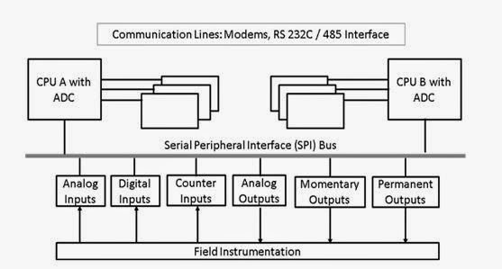
Figure 2.2
Schematic diagram of Foxboro Intelligent Automation (IA) System
Opening up the DCS architecture (software and hardware) for third part application brought in, along with advantages, a number of legitimate concerns in the industry. Among these were the applicability UNIX as OS concerning its reliability which required 7 days per week, 24 hours per day operation. Problems associated with redundancy of operation were to be convincingly addressed.
Such OS require specialized knowledge for maintenance which is not typically found in the process control community. Reliability of existing RDBMS against high demands of a real-time process information system which need to store hundreds to thousands of process values and events each second was of concern too.
By beginning 1990s, the DCS suppliers were gearing up to bring in advanced versions which were capable of interfacing with plant’s ERP system with truly distributed computing architecture. The earlier ‘legacy system’ DCS installed and commissioned since 1970s from these manufacturers, which were simply emulating the functionality of panel board were put to modification for use to control processes as well as to improve the process operation.
This was needed because the market requirements for distributed control systems and the emphasis for innovation began shifting from control to information management.
While there were revolutionary developments on DCSs, several corollary computer based automation systems were emerging with rapid transformation in the concept and technology because of the exponential growth and innovations underway in computer and IT fields. These included:
-
Programmable Logic Controllers
-
Computer Aided Manufacturing Systems
-
Supervisory Control and Data Acquisition Systems (SCADAs)
-
Plant Information management systems (PIMSs)
-
Direct Digital Control Systems (DDCs)
-
Specialized control systems for various requirements, such as safety override systems, batch weighing and blending systems, packaging line control, material transport systems, specialized equipment,
-
Specialized information systems like plant maintenance, document management, production scheduling, inventory management, cost accounting etc.
Microsoft entered the related field as the software infrastructure, around mid 1990,s with virtually monopolistic market position in the personal computer market. These were available at a small fraction of the cost and are sold by the tens of millions each year. Microsoft created an attractive desktop paradigm, popularly known as Windows, for viewing and navigating through complex information.
Most importantly, it created and integrated a complete operating, infrastructure support and application-development environment around a central framework, known as Distributed Component Object Model (DCOM) software architecture.
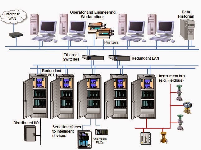
Figure 2.3
Architecture of an advanced Distributed Control System (DCS)
Microsoft’s rapid application tools (RAD) Visual Basic and Visual C++ coupled with ActiveX tools, with the ability to “drag and drop” application objects previously developed or purchased from another party, made complex and highly specialized applications affordable for users.
Independent application developers were developing specialized applications using Microsoft’s software infrastructure, at a small fraction of previous prices. There was significant concern, however, about the consistency, reliability, robustness and availability of such components considering that Microsoft’s products were not designed for the automation market.
The size and complexity of these products coupled with the maturity of the product (as compared with, say, UNIX) and the rapid pace at which these products were evolving required careful scrutiny.
With all technological developments, however, most DCSs at this point exclude from the computer based operation mechanism those applications that directly affect equipment operation or could endanger the safety of process operators. .
Among these applications are process control or other critical event processing, such as safety shut-down systems etc. These are still the domain of more deterministic technologies.
2.4 Present market trends in DCS
The DCS manufacturers are focused around the construction of systems which specifically include:
· Standards-based independent subsystems like intelligent Fieldbus devices
· Internet and Web technology into the DCS domain
· Object-oriented software components and containers
· Process automation and manufacturing embedded into plants ERP systems
2.4.1 Standard bus-interfaced Intelligent Devices
The open standards of DCS subsystems helped vendors of I/O systems to seamlessly connect their intelligent devices (for measurement and control purposes) to the DCS manufacturers system. The interface is through standard Fieldbus technology.
The smart devices connected by means of the standard buses to the DCS has embedded intelligence needed for simple regulatory and discrete control on the primary sensing devices ( say a smart temperature transmitter) and actuating devices (for example, a control valve). This eliminates the need for the DCS to perform routine process and discrete control.
The benefits of open Fieldbus standard for intelligent devices include:
-
Multiple physical parameters are measured and communicated in a time-multiplexed manner over a (normally two wire) digital transmission line, thereby providing more information at a reduced cost
-
Smart devices are capable of providing more information regarding the field status, thereby eliminating middleware and consequently less maintenance problems
-
The multidrop nature of serial Fieldbus and the multiplexed nature of digital transmission make wiring simple and associated hardware (like junction boxes etc.) mostly eliminated; this causes reduction in cost and maintenance.
-
Third party sourcing of intelligent devices from many vendors ensures wider selection choices and competitive pricing of sub systems.
2.4.2 Internet and Web Based Technology
The Internet technology (including Intranet, Extranet) is another technology area which created a great impact on all computer based automation products and systems including DCS. With Internet technology, DCS became a real-time manufacturing component of a supply chain model of a corporate wide enterprise management program.
DCS could now furnish timely information about product availability and manufacturing capacity information to corporate-level planning and decision management systems (the Management Information System).
This decision making regarding balance between flow of material and other resources against production can now be done in the most efficient and profitable manner.
Internet technologies also economically extended the information sharing capabilities to portable devices carried by operators and made accessible at any place and at any time.
Such mechanism could be effectively utilized by plant maintenance, engineering, and supervisory personnel and provide access to equipment drawings, material and safety data sheets, video clips of setup procedures, video or voice communication, and so on.
The security aspects associated with Internet technology supported permission enabled communication among plant workers or in fact anyone logged on to the Internet. Web technology supported information sharing through portals in static and interactive manner with text audio and video link facilities.
2.4.3 Component based Object Oriented Software Technology
Component and object-oriented software architectures have been successful for many years in the commercial computing world, but now these methods are making their way into the process control and DCS software communities.
The concept of component-based or object-oriented development originated in the IT world. Its goal was to provide tools that would release the developer from mundane, repetitive program tasks, while at the same time maximizing reuse through the development of common components.
The object-oriented approach to development enables simple drag-and-drop, click-to-select, or fill-in-the-text-box techniques. In most cases, this approach is easier than modifying scripts line-by-line. In addition, the number of syntax and run-time errors is minimized because the integrated development environment enforces system-specific rules. Users can develop objects once and then reuse them many times in the current application as well as future projects.
In component object-based DCS applications, application objects contain aspects or parameters associated with the device they represent. For example, a valve object can contain all the events, alarms, security, communications, and scripting associated with a device. Objects do not just represent plant equipment.
They can also model common calculations, database access methods, key performance indicators, condition-monitoring events, ERP data-transfer operations, and a variety of other production and performance management tasks. Because these operations are modular, it is easy to add them to any and all parts of the application.
For example, if there is a standard way your organization calculates and initiates a maintenance work order for a pump, you can encapsulate this function as an object and use it with any pump in the application.
The three popular industrial strength object oriented frameworks with sufficient technical prowess are Microsoft’s Visual C++/COM/ATL/MFC; SUN Microsystems’s JAVA/SWING, and the C++/STL ANSI Standard.
Of these, Microsoft’s framework is the most mature and well developed, the ANSI Standard is the most open and available for any platform, and SUN’s is the most compliant for network centric (the Internet) development, particularly Internet appliances.
2.4.4 Integration with Business System
The present day DCS system has been mostly relieved of the mundane activities, for example the functions associated with IO activities. These are, as discussed above, primarily under the purview of external systems.
Instead, the functions that were typically thought of as external to the DCS, like delivery of operator work instructions, feeding interpreted information to the MIS of the plant etc are now being incorporated into the DCS (see Figure 2.4). The DCS therefore additionally perform software functions in distributed computing environments which relates to:
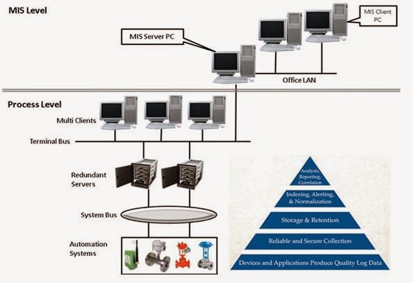
Figure 2.4
DCS integrated with the plant’s Management Information System (MIS)
-
Information; function associated with capturing, validation, and accessing all information generated at the plant regardless of its source, purpose, or user. This is an independent activity and works as standalone feature of the plant.
-
Application; these are activities that transform, translate, or otherwise represent the context of the information and
-
Presentation; concerned with the activities needed to view information the way user would find it appropriate and useful.
2.5 Basic DCS Specification
The following table (2.1) is the generalized specification of a commercially available Distributed Control System:
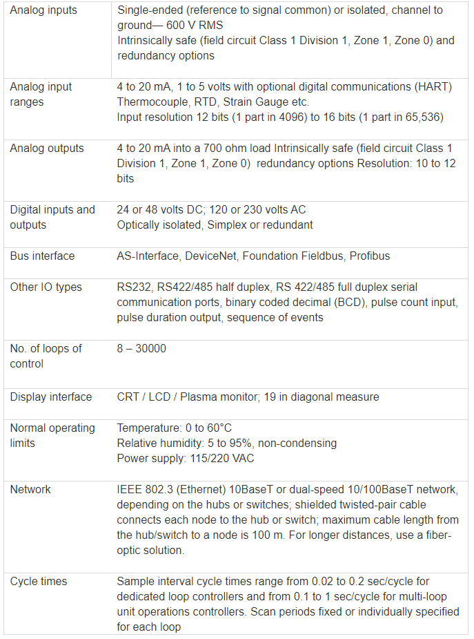
Table 2.1
General specification of a typical Distributed Control System
2.6 General description of a commercial DCS
The number of control loops in full-scale plants may be several hundreds. For such large processes, the commercial distributed control system is more appropriate. Some of the popular vendors who provide these DCS systems are Baily, Foxboro, Honeywell, Rosemont, Yokogawa, etc.
Conceptually, the commercial DCSs are similar to the simple PC network. The basic difference between the two types are that the DCSs, the hardware and software are quite flexible in the sense that these are easy to modify and configure, so that the system can handle a large number of loops effectively simultaneously.
Besides, the commercial DCSs are equipped with optimization, high-performance model-building and control software options. Thus a competent engineer with adequate knowledge of modern control systems can quickly configure the DCS network to implement high performance controllers.
The schematic diagram below (Figure 2.5) is of the DCS network where various parts of the plant processes and several parts of the DCS network elements are connected to each other via the data highway (Fieldbus). Although the diagram shows one data highway, in actual practice there could be several levels of data highways.
A large number of local data acquisition, video display and computers can be found distributed around the plant. They all communicate to each other through the data highway. These distributed elements role in monitoring and control of the plant process may vary according to assigned responsibilities. For example, those closest to the process handle high raw data traffic to the local computers while those farther away from the process deal only with processed data but for higher level hierarchy users.
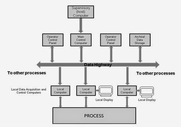
Figure 2.5
Schematic diagram showing the data highway concept of DCS
The data highway is the backbone for the DCS system. It provides information to the multi-displays on various operator control panels sends new data and retrieve historical data from archival storage, and serves as a data link between the main control computer and other parts of the network.
The supervisory (host) computer resides on top of the hierarchy. Most of the higher level functions are performed by the host computer. These include optimization of the process operation over varying time horizons (days, weeks, or months), carrying out special control procedure such as plant start up or product grade transition, and providing feedback on economic performance.
With such a configuration of the DCS it can now be used as powerful tool for automation of the production process of any large commercial plant. The engineer or operator can utilize such a system to:
-
Access a large amount of current information from the data highway.
-
See trends of past process conditions by calling archival data storage.
-
Readily install new on-line measurements together with local computers for data acquisition and then use the new data immediately for controlling all loops of the process.
-
Alternate quickly between standard control strategies and readjust controller parameters in software.
The design / project engineer can use the flexibility of the framework to implement the latest controller design ideas on the host computer or on the main control computer
In the common DCS architecture, the microcomputer attached to the process are known as front-end computers and are usually less sophisticated equipment employed for low level functions. Typically such equipment would acquire process data from the measuring devices and convert them to standard engineering units.
The results at this level are passed upward to the larger computers that are responsible for more complex operations. These upper-level computers are freed from low end work and are programmed to perform more advanced calculations.
2.7 Advantage of DCS Systems
The core concept of functional hardware distribution of DCS itself is one of its major advantages as it provides flexibility in system design, ease of expansion, reliability, and ease of maintenance.
A big advantage compared to a single-computer system is that the user can start out at a low level of investment and gradually develop / expand as the demand arises and expertise and acquaintance of the user develops with DCS systems.
Another obvious advantage of this type of distributed architecture is that complete loss of the data highway will not cause complete loss of system capability. The local units can still continue operation with no significant loss of function over moderate or extended periods of time.
.
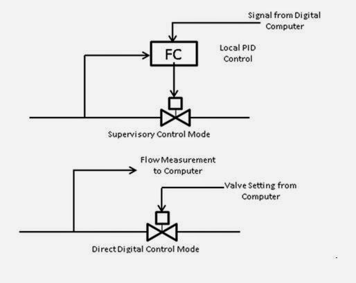
Figure 2.6
Conventional supervisory control mode replaced with DDC mode in DCS
The DCS network allows different modes of control implementation such as manual / auto / supervisory / computer operation for each local control loop. In the manual mode, the operator manipulates the final control element directly. In the auto mode, the final control element is manipulated automatically through a low-level controller usually a PID.
The set point for this control loop is entered by the operator either locally or at the host computer end. In the supervisory mode, an advanced digital controller is placed on the top of the low-level controller as shown in Figure 2.6 above.
The advanced controller sets the set point for the low-level controller. The set point for the advanced controller can be set either by the operator or by means of steady state optimization. In the computer mode, the control system operates in the direct digital mode shown above
One very important advantage of using DCS system is the flexibility associated with digital control algorithms. Some of the benefits of digital control application are:
-
Digital systems are more precise.
-
Digital systems are more flexible; the control algorithms can be changed and control configuration can be modified without having rewiring the system.
-
Digital system cost less to install and maintain.
-
Digital data in electronic files are easier to deal with. Operating results can be printed out, displayed on color terminals, stored in highly compressed form.
2.8 DCS Selection Criteria
As discussed above, the demand of the user from DCS system has expanded substantially; it’s no more seen merely as a panel board replacement. With advent of newer technology and phenomenal growth in software field with major players associating to deliver more intelligent logical systems the selection of appropriate DCS system is rather complicated.
The selection criteria for a DCS should therefore relate more to its intended use than the scope of its capabilities. The requirements definition should consider all of the intended users and consumers of information produced by the system.
The selection itself is a strategic decision for plant and therefore potential benefits for each department should be carefully explored in a series of meetings, surveys, and is associated with series of trainings and workshops.
2.8.1 Selection based on Economic Benefits
The fact remains that for the owner of the plant the economic benefits is the first and foremost point of consideration while incorporating a new DCS or switching over from conventional system to a DCS based system.
The first step in any analysis is therefore to completely define and quantify direct economic incentives that justify the project; described to as much detail as possible. Secondly identify any ancillary (indirect) benefits expected, whether economic or otherwise.
Finally, potential users of the system or consumers should be surveyed for utility of the information produced by the system to determine their expectations and requirements. The total set of requirements are then carefully listed and described with an economic value placed on each item.
The requirements of the users which don’t lend significant financial return should be evaluated by identifying alternative means to achieve the required results.
2.8.2 Selection based on Detailed Functional Specification and Systems
Requirement
It is obvious that the functional requirements (specification) of the DCS are associated with economic benefits desired out of those functions. Therefore each functional capability should also identify the set of economic benefits that are dependent on it.
An example of economic benefit based functional requirement may be like specific requirement of a particular section of the plant where it wishes to make an annualized savings of ‘X’ amount by preventing material losses of a particular ingredient by 10% caused by, say, tank spillage.
The Functional Specification for the above requirement include high-level indicator on all material tanks with a high-level alarm setting for, say, 90% of capacity and automatic shut-off of (shut-off) valves at 95% of capacity.
Upon occurrence of such abnormal condition, audible alarm would sound and notification on screen and if condition further deteriorates lead to automatic shut-off of filling system. Abnormal conditions including reasons for abnormalities would be logged and an interpreted conclusion (say regarding scheduling maintenance) may be forwarded to strategic level user.
The System Requirement therefore have to include resources for generating alarm notifications to process operators, supervisors, or both by posting a message at their workstations, triggering a control event, or generating an entry into an abnormal event log that includes the time, tag, alarm condition, and an attached message.
Thus consideration must be given to the physical plant topology, process environment, and process equipment attached, including device specifications and I/O lists, operator workstation locations, and so on.
To generalize on systems requirements, the following points, shown in tabular form (Table 2.1) should be taken into consideration:
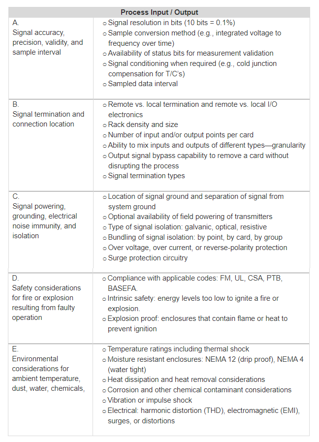
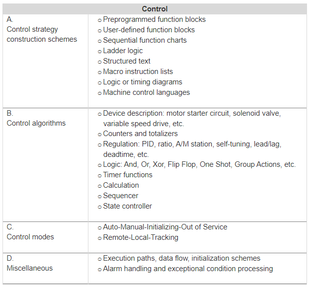
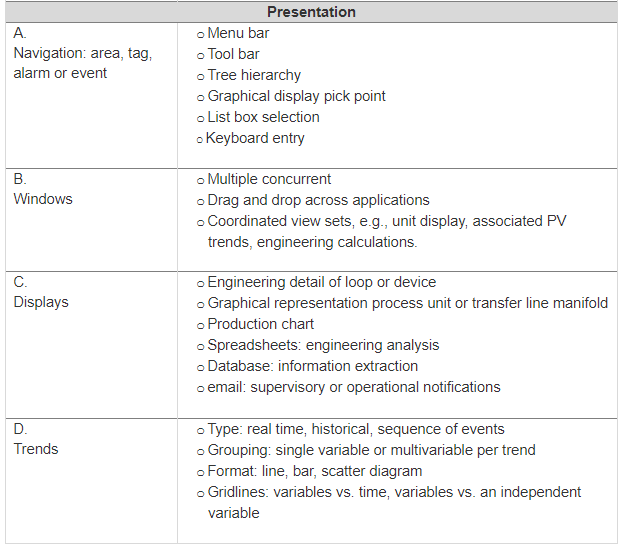
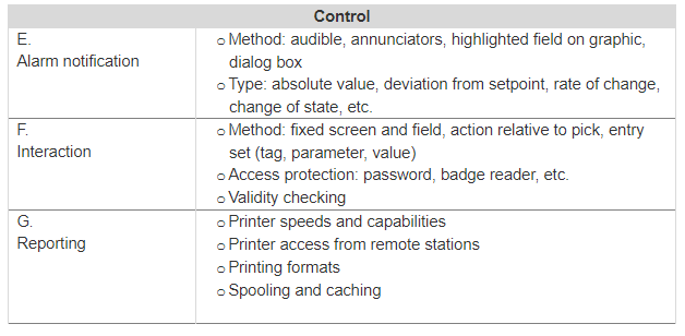
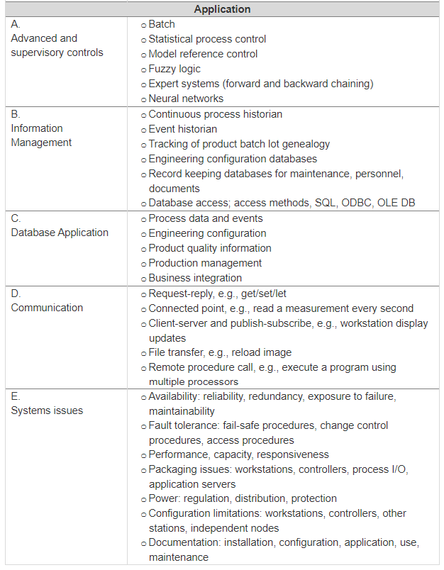
General system requirements of a typical Distributed Control System
2.9 DCS Architecture
The major components that make up a DCS process control system are illustrated in Figure 2.7 below. The description of the various components of the system is furnished below.
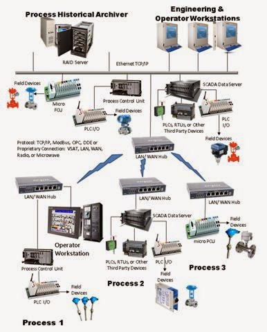
Figure 2.7
Schematic diagram of a Distributed Control System showing the basic components
2.9.1 The Engineering Workstation
The Engineering Workstation (EWS), a typical picture of the same may be seen in Figure 2.8, is for project development, including configuration of graphics, logic, alarms, security, etc.
Typically, the EWS is a PC running Windows NT/2000/XP; these OS are often preferred because of the broad support available to the manufacturers. These are typically made up of standard off-the-shelf personal computers (PCs), standard keyboards, mice, and CRT or LCD monitors.

Figure 2.8
Engineering Workstation; Picture courtesy ABB Control
The engineering workstations are the work centers for the operators. The operator can monitor the details of process operations with the consoles. Making use of the fast and accurate translation of raw data into useful trends and patterns, operators decide on the actions required for controlling the process.
Operators enter the set points and other process parameters with the help of the key boards connected to consoles. The console is also connected to the peripherals such as discs, tapes, trends recorders, printers, plotters etc.
The video display
The process monitor (also called VDU), is usually 19 inches diagonal in size, multi color television tubes, using dot matrix character generators. Some DCS are smaller (14 inches), monochrome screens. A few systems use 25inches diagonal screens for wall mounted displays, observable from the control room working area.
Today, the latest feature is the touch sensitive screen which gives the operator the ability to call up, for example, a group display from an overview display, by touching the portion of the screen where the group picture is located. One type of touch screen uses a grid of conductive material that changes circuit capacitance when a crossing pair is touched.
The material is embedded in a sandwich of transparent plastic. Another type of touch screen uses a grid of infrared light beams. Touching the screen breaks two crossing beam and triggers an appropriate response.
2.9.2 Process Historical Archiver
The Process Historical Archiver (PHA) copies the values of tags and other pertinent associated data, while a project is running, to an Open Data Base Connectivity (ODBC) -compliant database; a schematic diagram of the same which is linked to a typical process, is shown in Figure 2.9 below .
The values in the database can then be manipulated, examined, queried, used for rule-based decision making, and many other data analysis tasks. Using exception-based technologies, the data historian archives more data with less bandwidth.
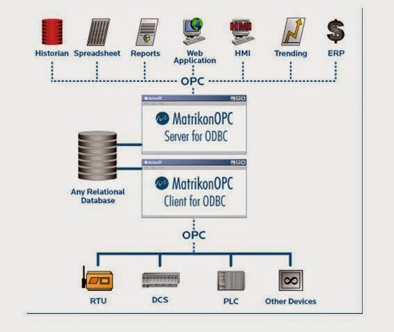
Figure 2.9
ODBC Process Historian architecture diagram; Picture courtesy Matrikon OPC
The Data Historian supports run-time archiving of project data to a disk file (database) that is compatible with the Microsoft ODBC standard.
The system supports any standard ODBC-compliant database (e.g., MS SQL Server, Oracle, etc.) and can be accessed using standard SQL queries. ODBC-compliant database managers, report writers, expert systems, custom software, and other applications can be used to read and manipulate the archived data.
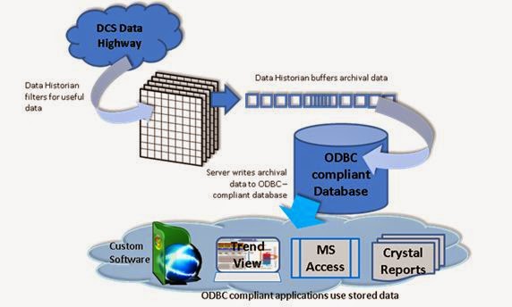
Figure 2.10
Run-time archiving of project data on ODBC compliant database
The Data Historian delivers the best of both approaches. It determines which data to save to the database using a method known as exception-based archiving (see Figure 2.11 above). The exception-based archiver examines the data values associated with archived tags.
If the data has not changed since the last sample, or has not changed more than the user-configured dead-band, then there is no archive entry to the database. This approach archives all data, minimizes the amount of space required to store data, and does not need to rely on statistical compression in order to reproduce that data.
It is quite obvious that acquiring more of the useful data ensures more accuracy; however, the same would require much larger bandwidth provisions. The bandwidth requirement is more when accessing archived data from remote nodes.
2.9.3 Process Control Unit
The Process Control Unit (PCU) directly scans and controls multiple I/O modules and executes event-driven logic. The PCU runs the sequential and regulatory control schemes downloaded to it from the Engineering Workstation.
These perform logic processing according to pre programmed schemes and in response to operator commands. The PCU optimizes network efficiency by relying on exception-based data reporting strategies in communicating with the DCS’s Operator Workstation and other PCUs. Real-time information is stored in memory for global use throughout the DCS control system.
The flexibility of such technology allows the present day PCUs to directly connect to standard, off-the-shelf I/O subsystems from different vendors
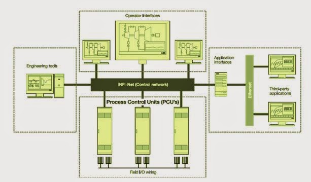
Figure 2.11
Schematic diagram of a DCS system showing the Process Control Units; Diagram courtesy ABB
The PCU runs on processors available from a variety of manufacturers in a variety of form factors. This includes PLCs for ultra-reliable performance as well as ruggedized industrial controllers for cost-efficient architectures.
Real-Time, Multi-Tasking Operating System
Each Process Control Unit is directly connected to the same network as the Engineering and Operator Workstations. The PCU may be selected to operate under various operating systems, such as Linux, QNX, UNIX, Windows, etc.
The plant may choose the OS best suited for its requirement; for example the OS may be either ultra-reliable, real-time, multi-tasking operating systems or cost-efficient industry standard operating systems with broad connectivity support
Depending on the need of local data storage, PCU can be equipped with flash disks, non-volatile memory, and an optional internal backup power supply to help ensure continuous processing in the harshest of environments. For additional reliability of operation, there are provisions for redundant PCUs and redundant I/O points.
At run-time, the PCU software receives commands and data from one or more operator workstations and/or one or more input/output interfaces that communicate with field devices (e.g. pumps, valves, etc.). It then processes and solves in real-time all logics generated during the project development phase. The manipulated results are communicated, once again, in real time to the Operator Workstation and/or input/output interfaces
Event-Driven Logic Processing
Logic processing is performed by the field control units according to the schemes developed during project configuration on the Engineering Workstation. The processing is completely event-based.
Every device configured in a device diagram is represented in a device table residing on the appropriate field control unit. All the logical relationships are represented in a device-specific event list that logically relates source (occurrence) and destination (triggered response) events.
When an event occurs at run-time, the logic processing engine uses the appropriate event list to determine what action (if any) to execute. That action may, in turn, trigger other events and actions. The real-time executive ensures that critical control functions take precedence over other operations and that logic is executed in the correct sequence.
Real-time information and device control status are stored in the control unit’s logic solver. Data updates are reported by exception. This frees the system from the scan rate limitations that can affect real-time processing and reporting of data at the Operator Workstation. It also minimizes network traffic allowing the field control units to be located remotely.
Advanced field control units supports I/O from different vendors in Each Unit
Standard vendor-manufactured I/O scanner cards are plugged directly into the field control units that are based on industrial controllers. These cards provide access to I/O networks, which are scanned directly by the control units. PCUs based on PLCs can directly scan just about any I/O supported by the PLC.
2.9.4 Data Server
The Data Server is the interface link of DCS with PLCs, Fieldbus technologies, RTUs, PLC I/O, and other third-party devices.
The Data Server can execute sequential and regulatory logic and directly scan supported I/O. It can also act as a data gateway allowing DCS to work with just about any device that are open systems compatible.
Typically, the data server is a ruggedized industrial computer running on Windows 2000/XP or other standard OS, although direct I/O scanning is run under some real time operating system.
The Data Server runs the sequential and regulatory control schemes downloaded to it from the Engineering Workstation. It performs logic processing according to those schemes and in response to operator commands. It also directly scans supported I/O.
It is a generalized, flexible, and user-configurable application designed to interface DCS system to other control systems, proprietary protocol drivers, specialized software, and such devices as PLCs, RTUs, flow computers, intelligent valve controllers, Fieldbus, etc.
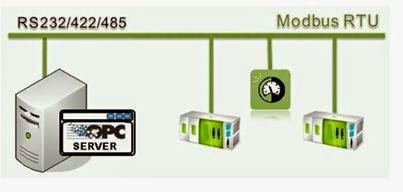
Figure 2.12
Diagram of a Modbus compliant OPC (data) Server which communicates with DCS system from multiple vendors; Diagram courtesy CommServer
Software protocol drivers used to match with third party installations run as separate tasks on the data server and communicate to devices external to the control system, such as PLCs, RTUs, flow computers, intelligent valve controllers, Fieldbus, etc.
The data exchanged with I/O, external devices, and other software systems is then “served” to the DCS database so the data can be used by logic, graphics, and other applications executing in the systems environment. Moreover, all commands and set points initiated from the DCS system’s Operator Workstation are routed to the data server application which, in turn, routes them to the appropriate external application or device.
The role of the data server, which is typically run on a ruggedized industrial processor, may be summarized as under:
-
Supports both serial and TCP/IP connections
-
Supports off-the-shelf, industry-standard ActiveX, OPC, and Dynamic Data Exchange (DDE) drivers
-
Communicates with any RS-232-compliant equipment
-
Supports enabling/disabling of COM ports and polling lists
-
Supports multiple ports
-
Supports multi-drop slaves configuration on the RS-485 communication bus line
-
Allows creation of a poll list for each port
-
Supports unsolicited write
-
Can be supplied in a redundant configuration
2.9.5 DCS Networking and Communication
The present day DCS supports redundant and non-redundant fiber optic and Ethernet local networks using the TCP/IP networking protocol for standardized, advanced application connectivity.
DCSs can be networked via satellite (VSAT), local area network (LAN), wide area network (WAN), radio, or microwave using TCP/IP, Modbus, OPC, DDE, or proprietary protocols. The LAN can use single or redundant Ethernet or fiber optic technology.
However, regardless of the technology chosen, the functioning is exception-based reporting techniques that minimizes network traffic and maximizes bandwidth usage. As a consequence, it is now economically feasible to locate remote control functionality of the DCS closer to the equipment being monitored and controlled.
The report-by-exception delivers accurate data where it’s needed but significantly reduces network traffic and eliminates the need for specialized and expensive communications hardware and software.
The copies of the entire database may be economically distributed to multiple locations, or, it may be distributed to selected locations depending upon the security or the hierarchy aspect of the distributed data; an action decided at the time of programming
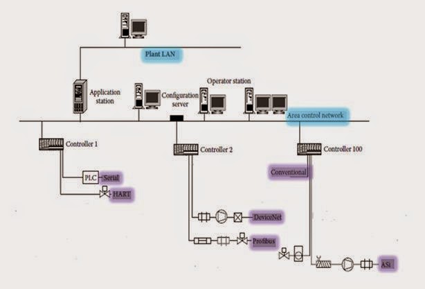
Figure 2.12
DCS topology integrating multiple I/O buses into a single system
The LAN/WAN can be extended to other sites inside or outside the plant using such remote communications technologies as satellite, radio, microwave, and dial-up running such standard protocols as TCP/IP, Modbus, OPC, DDE, etc.
2.9.6 The Process section
This area (process 1 in Figure 2.7) illustrates processes that require significant monitoring and control. A local operator uses the color graphic Operator Workstation to monitor and control the process, while the Process Control Unit executes sequential and regulatory control logic.
As usual, exception-based technology is used to transfer only data that needs to be archived or shared with other nodes, thus minimizing communications traffic. Local monitoring and control also helps insulate this site from failures elsewhere in the system. An optional redundant configuration makes even local shutdowns rare.
For unmanned process location (shown as process 2 in Figure 2.7), where the process does not require a local operator, the controls serve as a true data concentrator. A data server installed at this location which interfaces the system to PLCs, Fieldbus technologies, RTUs, PLC I/O, and other third-party devices.
This data server can execute sequential and regulatory logic and also directly scans supported I/O. It can also act as a data gateway allowing DCS to work with just about any device compatible with the system.
Just like the processes 1 with operator control, the data servers at unmanned locations are configured to minimize communication traffic, isolate the location from failures elsewhere, and are available in a redundant configuration.
Another type of process area (process 3 in figure 2.7) requires local control but does not necessarily need an onsite operator. These have micro Field Control Units, which are basically small PLC that executes sequential and regulatory logic and directly scans onboard I/O.
These may work as replacement to RTUs at a significant reduction in cost and power consumption; besides it can also provide local intelligent control of devices, which normally RTUs can’t do.
2.9.7 The Operator Interface
The operator interface features high-resolution graphics and familiar Windows GUI interaction. The operator interface running on the operator workstation has the following features:
-
It allows operators to monitor detailed activity for many types of devices and send commands using command windows and group displays
-
It displays optional project screens created during project development and makes them dynamic based on real time data
-
It logs alarms and other events, displays alarm and log messages, and lets operators acknowledge alarm
-
It trends real-time and historical data
-
It allows the authorized operators monitor and manually override device logic
-
It also displays the status of communication between the operator workstation and process control units, which helps the operator diagnose the cause of communication interruptions
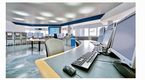
Figure 2.13
Picture of ABB Symphony control room with Workstations mounted with (GUI based) operator interfaces.
The operator interface is usually through high -resolution color graphics and the Windows graphical user interface. Flexibility is ensured via selected operating characteristics that are configurable at run-time.
Standard features include simultaneous display of multiple project graphics screens, drop-down menus, and run-time configuration dialog boxes. Consistency is ensured because most monitoring and control functions are automatically generated.
For example, command windows are generated automatically during project configuration and present a consistent appearance. Figure 2.13 above shows operator interface through a series of consoles mounted in a control room.
2.10 DCS Configuration
In a DCS system, using an integrated, object-oriented configuration tool, a control engineer can implement complex regulatory, discrete, and sequential control without extensive programming. Here graphical objects incorporating control capabilities and configured characteristics are dropped into places of the control logic. This method is used to configure sections:
-
Hardware architecture; including operator workstations, field control units, individual I/O points, data servers, etc.
-
Logical control relationships and physical interconnections among devices within a facility or process
-
Logic behind user-definable devices, such as pumps, valves, and motors
The configurations begin with the Project Configuration editor as shown in Figure 2.14 below
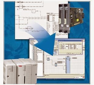
Figure 2.14
The project configuration editor, hardware to software; Picture courtesy ABB INFI 90 DCS System
Project architecture is configured from the Insert menu; it configures different segments of DCS system including workstations, Process Control Stations, I/O, etc. The configure menu can undertake the following:
Configure device logic, tag definitions, run-time graphical behavior, etc. for devices and store this device definition in a template . The template can be used to insert multiple new device definitions into control logic, which is called a device diagram. Each new device inherits all the characteristics of the template, yet each new template-based device is unique and can be further modified.
Create control logic that provides all control instructions to the project’s process control units (PCUs). The control logic is organized by device. Each device contains all the control logic, tag definitions, and HMI graphics associated with that device. The user can then arrange symbols representing each device in a device diagram to represent the control logic of a project.
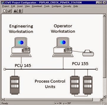
Figure 2.15
Screen shot of DCS configuration editor; Picture courtesy CSI Inc
Create project graphic screens using a CAD-like drawing editor. The resulting screens can contain dynamic objects that change color, position, shape, etc. in response to run-time data .
Organize command windows into group displays and then display these groups of command windows by specified name at run-time. Run-time command windows, or faceplates, provide a method of monitoring and controlling the process. The system is capable of automatically creating command windows for transmitters, controllers, and discrete devices.
Configure destinations for alarm and logging messages.
Configure Detectable Groups that can be used to enable/disable screen object clicks.
Define communication parameters for each workstation that will be monitoring the Archiver.
Specify or modify the project’s name, description, and network type.
Perform global TCP/IP address changes.
Configure function keys to show or hide screens in run-time.
Assign scripts to specific workstations. Scripts are the programs written in a language specific to a particular DCS. Scripts can cause defined actions to take place through pre-programmed instructions in the script itself or through operator action.
Customize user-defined device command windows. Command windows can include data from multiple devices. This data can be displayed in digital or analog format or as trends on the display.
Use Dynamic Data Exchange (DDE) to pass information between the project and any DDE compliant software package.
Specify a PCU’s router address that can be used to detect whether a PCU or its router is down.
The Security menu allows to:
-
Configure project-specific security.
-
Login/logout users
-
Set login default preferences.
Other miscellaneous menus allow the users to:
-
Customize symbol graphics.
-
Download projects to workstations, field control units, and field data servers after configuration.
-
Download updated device definitions and logic to PCUs without taking the project offline.
-
Import and export hardware definitions
-
Print the project configuration, including the architecture drawing, the complete hardware configuration, control logic, and device configuration.
The major functionality of the project configuration are as under:
2.10.1 Architecture configuration
The project is named through this level of configuration. Also, type of network for the project is chosen, the project’s hardware components are selected, and the communication paths are set up during this process.
The project name and network type are specified when a new project is created via the Project > New menu item. Workstations, printers, field control units, and data servers are inserted by clicking on the appropriate toolbar button or menu item.
A dialog box appears in which the user can enter configuration information. On exiting the dialog box, the new object is automatically inserted into a diagram of the architecture.
Configuring Workstations, Archiver, Data Servers, and Printers
Workstations, Process Historical Archiver, and Data Servers require a node name, node address, and profile name. The workstation description is optional. The workstation profile associates a reusable set of security definitions with the workstation.
From the Workstation dialog box the user can
Configure communications parameters between this workstation and PCUs, as well as optimize communications over wide-area networks (WAN).
View and modify the Dynamic Digital Exchange (DDE) sources, logging devices, and alarm groups that are assigned to the workstation.
Designate the run-time applications that will start automatically when Run-Time is initiated.
Printers can be associated with a selected workstation and require only a name and port designation.
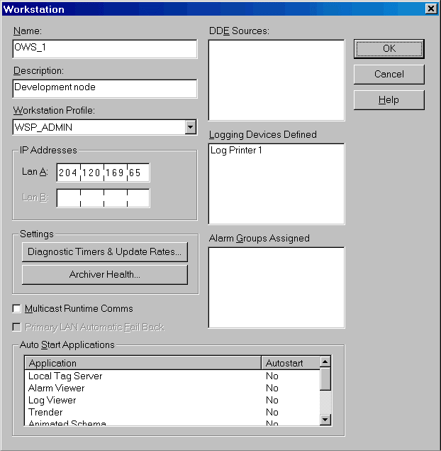
Figure 2.16
Screen shot of Workstation dialog box; picture courtesy CSI Inc.
Process Control Units (PCUs) and associated IOs
This dialog box is designed for the operators to get access to appropriate amount of information as necessary for their requirements with provisions to add, change, and delete PCU and I/O definitions. As may be seen in the screen shot below, the left side of the Hardware Definition dialog box displays a telescoping list of all PCUs and I/O associated with the project.
The relationships among PCUs, I/O cards, channels, chains, racks, and modules are illustrated via a tree hierarchy. The hierarchy can be viewed by PCU or at user-defined location within the facility.

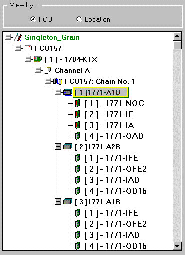
Figure 2.17
Screen shot of Process Control Unit and IO dialog box; in bottom is the enlarged view of PCU/IO
The right side of the dialog box, as shown above, displays a detailed definition of the item selected in the hierarchy view. For example, if a rack is selected on the left side of the dialog box, the right side displays the definition of that rack.
The module definition shows, among other things, a list of points available for later assignment to tags. As can be seen on the screen shot of module definition shown below, the first three points have already been assigned with tags.
I/O points are addressed via structured tag names; it is done so for logic configuration on the engineering workstation, for operator use on the operator workstation, and in the process control unit for logic execution. This replaces the traditional method of direct memory addresses found in Programmable Logic Controller (PLC) rung ladder logic.
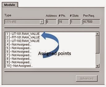
Figure 2.18
Screen shot of module definition
2.10.2 Device Diagram configuration
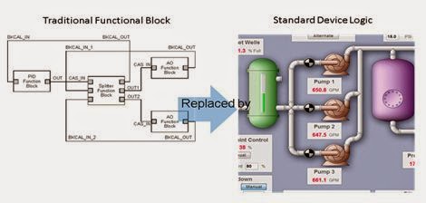
Figure 2.19
Relationship of device diagramming to traditional control programming technique
The device diagrams represent the master control logic programs that provide all control instructions to the project’s process control units (PCUs).
The present day device diagram combines the capabilities of traditional DCS function blocks with the sequential logic capabilities of user-definable devices that act as a replacement for PLC rung ladder logic. As such, regulatory, discrete, and sequential control is created with a single tool.
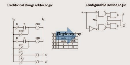
Figure 2.20
Traditional rung ladder logic replaced by configurable device logic
The configuration mechanism uses a drag-and-drop graphical interface to insert and configure devices from a library of user-defined device templates. These templates contain, among other things, all the logic and functionality underlying the devices represented in the diagram.
Additionally, the ability to customize the diagram symbols associated with devices allows device diagrams to graphically represent both logical control relationships and physical interconnections.
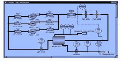
Figure 2.21
Screen shot of complete device diagram of a section of the process– picture courtesy CSI Inc.
The symbols that appear on device diagrams represent equipment and logical control schemes. They can be connected together in a way that indicates how they interact with one another — both logical control interactions and physical interconnections .
This makes it potentially possible to glance at a device diagram, determine what role a device plays in control. Interactions, and determine the physical interconnections for a process or facility
Components of Device Diagram
The following explanation is based on CSI Inc. Distributed Control System architecture. All the basic components of a device diagram are schematically represented in Figure – below. The diagram has named devices (control, computing, static, and user defined) and connection Lines (mechanical, static, analog end etc.). A screen shot of a device diagram under preparation is shown in Figure 2.22 below.
In this type of system, the user need not have to reprogram and reconfigure every device for every project; built in (industry standard) components are available for use with provisions to create custom solutions when necessary.
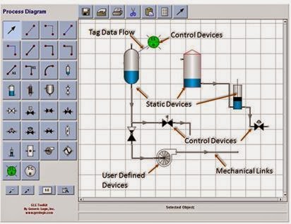
Figure 2.22
Device diagram showing process component, controls and interconnections
In a typical DCS system the following provisions are there under device diagram:
-
Availability of a wide range of pre-configured devices with built-in functionality
-
Provisions to modify certain device configurations and functionality
-
Availability of features to create custom devices with custom functionality
The devices are categorized under following heads:
Standard control devices , such as transmitters and controllers. The functionality of each control device is built in and does not have to be programmed.
Standard computing devices , such as selecting functions, limiting functions, and a calculation function. The functionality of each computing device is built in and does not have to be programmed, except for the calculation function, which allows you to specify a formula.
Static devices have no functional characteristics but may be needed to fully represent the physical characteristics of the plant or process. The symbol used to represent a static device in a device diagram can be user-defined.
User-defined devices such as pumps, valves, and conveyors; the logic, tag definitions, and symbols associated with these devices are fully configurable. User-defined devices replace rung ladder logic.
The symbols used to represent static and user-defined devices are fully configurable. A wide range of pre-drawn symbols as well as a symbol editor that can be used to modify existing symbols and create new ones are available for preparing device diagrams. The symbol editor can create user defined graphic symbols in project configuration or can import graphics from another drawing package.
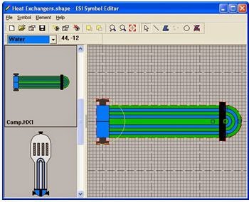
Figure 2.23
Symbol Editor – picture courtesy KB Eng. Inc.
Device and Tag Names; Unique tag names earmarked among devices via the device name, which may be composed of a device type, a hyphen, and a device ID. An example of device tag name is shown below in Figure 2.24
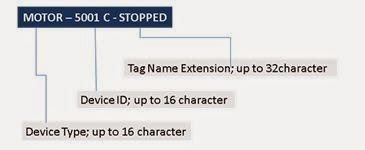
Figure 2.24
Typical Tag Name Convention complying with ISA standards
Device Connections; Connection lines indicate the physical and/or logical relationships among devices as has been shown below in:

Figure 2.25
Device connection; a flow transmitter connected to process through a static connection
-
Mechanical lines are thick solid lines; not associated with any control functionality. These lines only show the physical interconnection among devices.
-
Static lines (medium gray) indicate signal flow from the process to a device.
-
Tag data flow lines (dashed) indicate flow of data among devices.
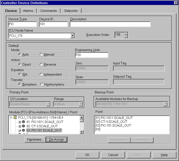
Configuring Control Devices
The control devices are configured based on widely accepted industry standards and, therefore, these are normally not separately defined.
For example, PID loop controllers perform an industry standard function that applies to control of many types of facilities or processes. The configuration is therefore done using graphical techniques and fill-in the- blank forms to configure each controller device.
A unique name is specified for the new controller device on the graphics of process control unit (PCU) where the logic for the controller device is solved, the point to which the controller device output is assigned, and a backup point is plotted.
The screen shot for one such controller being configured is shown in Figure 2.26 below. The definitions for alarms, set points, commands, and other default parameters are also filled on the form.
.
Figure 2.26
Controller device definition dialog box; screen shot courtesy CSI Inc.
Once the controller device is configured, it is clicked on the device diagram to indicate where the new device is placed. For a PID controller, say, it is not necessary to program it’s algorithm that defines the functionality.
The PCU software is pre-programmed with the PID algorithm and similarly, algorithms of other controllers, to execute it when called to do so.
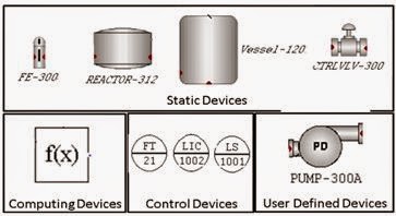
Figure 2.27
Different components of device diagram; tagged and configured
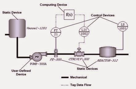
Figure 2.28
Fully functional device diagram made with configured components above
Graphic Editors:
Graphic editors provide mechanism to create the graphical user interface, or project screens, for the project. For example, the user can create a control screen that displays certain pumps and valves, graphically represents their logical and/or physical relationships, and monitor their status. The user can also send commands to them via command windows or other means.
Generally, the Editor is used to insert objects into the drawing area, manipulate the appearance and position of the objects, and apply run-time dynamics to the appropriate objects. Objects can be primitive graphics (lines, rectangles, circles, etc.), controls (buttons, check boxes, data-entry boxes, etc.), and bitmaps. In addition, previously created template graphics associated with specific devices can be inserted into the drawing area.
There are two types of graphics, namely the template graphics and the project screen graphics.
Template Graphics define certain default device characteristics, including logic, tag names, and graphics. When a user insert a user-defined device into a device diagram, the characteristics of that device is copied from the appropriate template to the new device.
The new device will have the same logic, tag name extensions, and graphics as the template and any other inserted device based on that same template. These characteristics can however be modified for each inserted device.
Project Screen Graphics can be as elaborate or as simple as the need require. The Editor produces a dynamic graphical representation of the process. The project screen can then be configured to display active process and instrumentation values, manually control tag values, and therefore turns into a dynamic illustration of the process. Figure 2.29 below is the screen shot of a project screen graphic
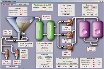
Figure 2.29
Example of a project screen created in graphic editor
Scripting
Scripting uses a programming language to initiate actions through script commands or operator actions at run-time.
A script may be assigned to any workstation or to multiple workstations, including data servers.
Scripts customize processes and visual effects. The user can read and write tag values, manipulate data, save and retrieve tag values, retrieve text from tags, and perform other tasks. Also with scripts, the user can perform tasks that logic cannot, such as launching third-party applications and manipulating text. Scripts can be used in any number of ways including:
Launching applications, such as Excel, Word, or Access
Placing data into a text file for import into another application which can then generate a formatted report based on that data
Using calculations to animate or move screen objects in a precise way
Writing a script is similar to writing a program in BASIC, Pascal, C, or other high level languages. Figure 2.30 below is the screen shot of a script editor.
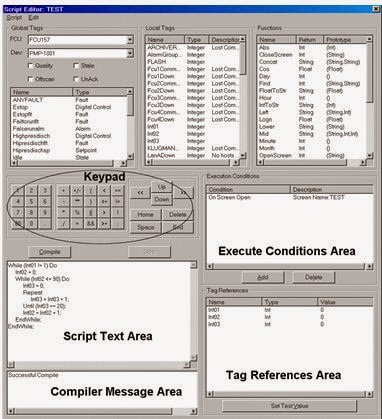
Figure 2.30
Screenshot of a Script Editor; screen shot courtesy CSI Inc.
2.10.3 Alarm and Logging configuration
DCS systems use object-oriented techniques to configure alarming and logging with minimal effort. User may create one or more alarm groups and/or logging groups. A logging group consists of a list of logging devices to be associated with that logging group.
Each logging device sends data to a printer or disk file. An alarm group consists of little more than a name for the group. Then one or more alarm groups are associated with one or more operator workstations.
Typically, up to 16 alarm priorities can be defined. These specify the color of alarm messages, whether or not an audible alarm is sounded when the tag goes into alarm, and whether or not acknowledgment is required. The alarm group, alarm priority and/or the logging group to be associated with each tag, as applicable, is then selected.
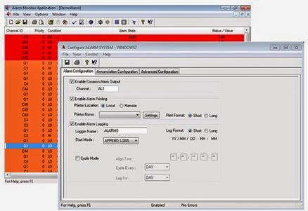
Figure 2.31
Configuring alarm system
Each alarm group, alarm priority, logging device, and logging group will be defined only once in a project. However, once the item is defined, user can create alarm and logging associations for thousands of tags simply by selecting a name from a supplied list.
DCS program would handle the task of matching the proper workstation or logging device with each tag at run-time. At run-time when activity occurs on a tag, that activity is logged via that tag’s group to the appropriate workstation, printer, and/or disk file.
2.10.4 Security configuration
Typically, the DCS systems have a flexible set of security functions and easy-to- use dialog boxes for security definitions. Certain functions are pre-defined as secure, i.e. they are protected from unauthorized use.
For example, secure functions include developing a project, starting or stopping a run-time project, sending commands to a device at run-time, acknowledging alarms, and archiving data etc. are all protected from unauthorized access. Project and security configuration are also secure functions. These functions can be used only if the logged-in user has security clearance to use them.
All run-time project graphics screens are also considered secure. However, the level of security can vary from screen to screen and from workstation to workstation. A user may have access to a given screen on one workstation but may not have access to that same screen on a different workstation.
Security is configured using object-oriented techniques that provide significant flexibility while minimizing the amount of required configuration.
User Access; in order to start project configuration or Run-Time configuration, a user must log in by providing the correct username and associated password.
Security Groups; security access is configured via security groups. Each user belongs to one security group. The security group determines who has access to the following tasks:
Starting and stopping a project in run-time
Archiving data and accessing that data
Sending commands and setpoint changes
Acknowledging alarms
Toggling tags on and off
Manually overriding tags in Device Diagnostics
Developing a project
Configuring security
Accessing project screens in run-time
Auto Log Off; Any Engineering Workstation or Operator Workstation can be configured to automatically log off after a user-specified number of minutes of inactivity, that is no keyboard or mouse activity. This adds another level of security that is independent of the operator.
2.11 Conclusion
The demands of process industries for immediate, available, and reliable information have made the distributed control systems to become the information provider to the manufacturing enterprise component of corporations.
To accomplish this, the users of DCS have adopted mainstream distributed computing technology. Open computing standards and component-based architectures facilitate the seamless integration of applications and information among the various business, production management, operations, and process control systems.
Distributed control systems, which were originally conceived as panelboard replacements, have, in course of time, dramatically improved their process information and management capabilities. Essentially all DCS’s on the market today offer a hybrid approach that uses open standards-based solutions such as UNIX or Microsoft Windows NT/XP for supervisory and production management applications.
This include information storage, retrieval and presentation, business application integration, and a comprehensive development environments, while continuing to employ proprietary hardware and software for their embedded computing requirements such as process control.
Rapid innovations for Internet (based) appliances require a similar responsiveness, availability, and fault tolerance in distributed control systems. This technology promises to eventually displace the remaining proprietary solutions for applications such as process control. These, however, will have to address the mission-critical and safety concerns that differentiate real-time control from general purpose computing, particularly in those situations in which safety is the key issue.
Source: IDC Technologies