The basic type of controller is the Feedback Controller .
Feedforward controllers also exist but are more complicated to implement. Here we will describe the use of feedback controllers.
In feedback control the variable required to be controlled is measured. This measurement is compared with a given setpoint. The controller takes this error and decides what action should be taken by the manipulated variable to compensate for and hence remove the error.
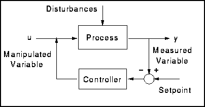
Figure 1 - Feedback Control Loop
The advantage of this type of control is that it is simple to implement. Not only does the feedback control system require no knowledge of the source or nature of the disturbances, but it also requires minimal detailed information about how the process itself works. Feedback control action is entirely empirical. So long as an adjustment is being made in the correct sense then the control system should remove the effect of an external disturbance.
The disadvantage is that the disturbance has to enter and upset the system before it is eliminated.
A feedback control loop can have one of two objectives.
- A servo control loop is one which responds to a change in setpoint. The setpoint may be changed as a function of time (typical of this are batch processes), and therefore the controlled variable must follow the setpoint.
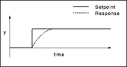
Figure 2 - Servo Control
- A regulatory control loop is one which responds to a change in some input value, bringing the system back to steady state. Regulatory control is by far more common than servo control in the process industries.
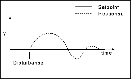
Figure 3 - Regulatory Control
Proportional Controller
The first type of controller that we will study is the proportional controller. This controller sets the manipulated variable in proportion to the difference between the setpoint and the measured variable. The bigger the difference, the greater the change in the manipulated variable.
The equation that describes a proportional controller is
![]()
where
- ut is the output from the controller, i.e. the adjustment
-
 is the constant of proportionality, ususally called the controller gain
- ud is the output of the controller at its design conditions, sometimes called the bias
- ys is the required value of y or the setpoint
- y is the input to the controller, i.e. the measured variable
The advantage of proportional control is that it is relatively easy to implement. However the disadvantage is that when implementing a proportional only controller there will be an offset in the output. Thus there is always a difference between the setpoint and the actual ouput. The reason why this is so can be shown by means of an example.
Example: Flow Through a Pipe (1)
Below is a diagram of the example.
- F is the flowrate through the pipe
- Fm is the measured flowrate
- Fs is the required, setpoint flowrate
- e is the error between the setpoint and measured value
- Fv is the valve position or controller output
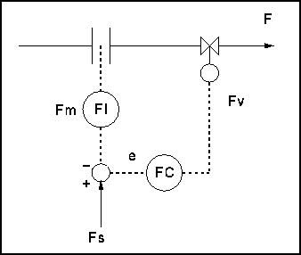
Figure 4 - Diagram of Flowrate Example
Therefore we can see that
![]()
Here

So

Let us assume to begin with that Fs = 50 and Fd = 50. If this is true then it can be seen from the above equation that F = Fs and there is no error. Note that this result is independent of the value of the gain.
However, let us now consider what happens when the value of the setpoint changes from 50 to 60 with Fd staying constant at 50. First the relevent equation is shown and then the table below summerises the results for different gains.
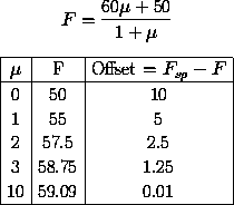
From the above example we can see the problem of using proportional only control, namely the offset. Note also that there must always be an offset. This is because to achieve the new steady state the term ![]() must have a value and so there must be an error. There are two ways of eliminating this problem.
must have a value and so there must be an error. There are two ways of eliminating this problem.
- Choose ud to correspond always to the correct output
- Make the gain very large
The first is hard to achieve since it requires very accurate knowledge of the process, and would require changes whenever the setpoint is moved.
The second leads to problems of rangeability and sensitivity. Suppose the gain is 10, then measurement noise of 1% of the total range will cause the control valve to move over 10% of its total travel. This is unacceptable.
Proportional-Integral Controller
To remove the offset integral action is required and so PI control is normally used. It works by summing the current controller error and the integral of all previous errors. It may be thought of as a way of automatically calculating the quantity ud . Proper tuning - described in a subsequent section - of the integral part of a PI controller can improve its performance.
If the error e is defined as
![]()
Then the equation describing a proportional-integral controller is
![]()
where
-
 is the reset time of the controller
Alternatively, we can differentiate this expression to get
![]()
Example - Flow Through a Pipe (2)
Again we will use the example of the flow through a pipe to investigate the nature of Proportional-Integral control.
As before
- F = y = u
- e = Fs - F
So
![]()
Since Fs is constant, this becomes
![]()
Or
![]()
Equations of the form
![]()
are very common and have well known properties. Their solution has the form shown below.
![]()
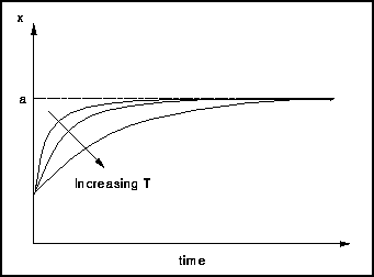
Figure 5 - Response Curve
We note that
- As time goes to infinity, x = a
- The rate of response of the system increases as T (called the time constant of the equation) becomes smaller
For the flow control system with integral action we see that
- F will eventually become equal to Fs
- This will happen faster if
 is small and/or
  is large