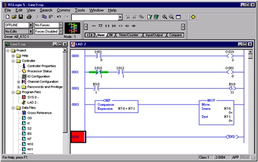
Every PLC has associated programming software that allows the user to enter a program into the PLC.
• Software used today is Windows based, and can be run on any PC.
• Different products may require different software: PLC5, SLC, and ControlLogix each require their own programming software.
Different PLC Languages
• Before a PLC can perform any control task, it must be programmed to do so. The most popular language used to program a PLC is ladder logic.
• In a conveyor system, we have several “requirements” to accomplish; for example, timing and counting parts on the conveyor. Each of these requirements must be programmed into the PLC so that it knows how to respond to different events.
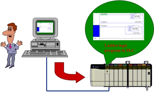
• The programmer develops the program, and connects their personal computer to the PLC through a network or cable and then downloads the program to the PLC.
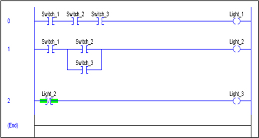
Ladder Logic Example :
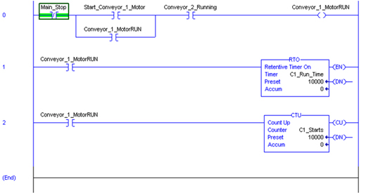
• Here, we can see an example of ladder logic. Each line of code is known as a “rung”. In this example there are 4 rungs, numbered 0, 1 and 2, and the end rung marking the end of the program.
• The PLC executes the program 1 rung at a time, starting with the first rung and then working down.
• Ladder logic rungs are basically IF-THEN statements. Each individual rung is executed from the left to the right. The outputs at the right side of each rung is set to a condition that reflects the status of the permissive contacts in a particular rung.
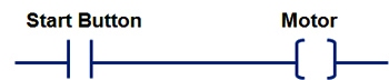
• This is a very simple rung of logic, from a PLC program :
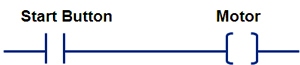
• The rung is read as :
-> If the Start Button is on , turn the Motor on . If the Start Button is off, then turn the Motor off.
-> Let’s take a look at this simple program in detail…

• In this example, if the actual Start Button is on , then the value of all the XICs named Start Button, in the program will be true (also known as a ‘one”, or “closed”).
• If the start button is off (not on) then the value of the Start Button XICs will be false (also known as a “zero”, or “open”).
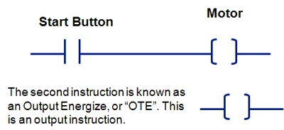
• This instruction turns on if the logic to the left of the OTE is true. If the logic is false, then the output will be turned off . The OTE commands a physical output located on a output module to turn either on or off.
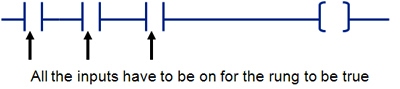
• If there are multiple XIC’s on the rung, then all would have to be on for the rung to be true.
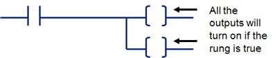
• If there are multiple OTE’s on the rung, then all would be turned on or off based on the rung condition (true or false).
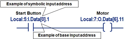
• The text above the XIC and OTE is the address associated with the instruction. PLC addresses may appear in many different ways depending on the PLC being used :
-> Start_Button
-> Local:2:I.Data[0].1
-> I:020/2
• The address is used by the PLC to tell exactly which input to read or which output to command.
I/O Addressing :
Since a PLC will be controlling real devices down on a plant floor, it has to have some way of communicating to the correct device. All PLCs use some sort of method of I/O Addressing to perform this function.
• I/O addresses are a means to tie a physical I/O point to a location in PLC memory.
• An input address will represent the state of an input device, i.e. the switch is on or off.
• An output address will represent the commanded state for a device. i.e., turn the motor on or off.

• Often, a descriptive name of the device connected to the I/O point is used in addition to, or in place of the base I/O address which describes the physical location of the module in the rack.
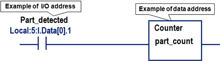
I/O Addressing vs. Data Addressing :
• I/O addresses are a means to tie a physical I/O point to a location in PLC memory. There are other addresses that do not connect to physical I/O, but are used to hold a value.
• Data addresses store a value used for functions like timers, counters, or calculations.
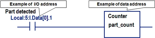
• In this example, parts on a conveyor are counted. The input, “Part_detected” looks at the I/O address of the actual sensor counting the parts.
• The counter references a data address, and accumulates the counts in that location in memory.
• Each time the “Part_detected” switch closes, the counter adds one more count to the area of memory called “part_count”.
Ladder Logic Example :
Next, we will take a look at an actual segment of ladder logic code. The code will be the code used to control our conveyor from the first lesson. Before we do that, let’s take a look at a few more ladder logic instructions :
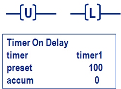
• OTL - Output Latch - turns on the output and keeps it even if the rung goes false.
• OTU - Output Unlatch - turns off the output when the rung is true.
• TON - Timer On Delay - when the rung is true the timer will run.
It will store the elapsed time in the “Accum” field (accumulator). As long as the rung remains true it will count until it reaches the preset value. If the preset value is hit the DN bit will go on (Don bit). When the rung goes false the timer will be reset.
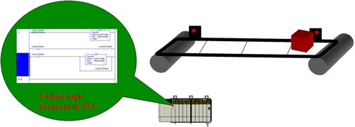
Programming a PLC – Conveyor example :
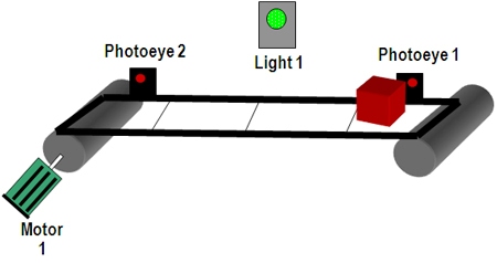
• Now let’s take a look at a simple program for a conveyor application.
• When a box is placed on the conveyor in front of Photoeye 1, Light 1,and Motor 1 will turn on, causing the box to move down the conveyor to the left.
• When the box passes in front of Photoeye 2, Motor 1 and Light 1 will turn off, stopping the conveyor.
Relay Ladder Logic Example :
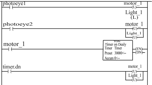
Here’s the program for the conveyor: The first line of code turns on the motor and the light when a box is detected by photoeye1. Likewise, the motor and light are turned off when photoeye2 detects the box in the second line of code.
The third line begins a timer when the box passes by photoeye1, and if the box does not pass by photoeye2 in 30 seconds (the timer counts in milliseconds), the motor and light are shut off by line 4. This is the indication of a jam condition.
PLC Addressing Examples :
• Logix Controller sample addresses :
- Motor_start - Binary Tag
- Tank_temp - Integer Tag
- Local:5:I.Data.0 - Input Tag (Local - same chassis as processor, in slot 5, is an input, data bit 0)
• PLC-5 sample addresses :
- B3:0/2 - Binary File
- N7:0 - Integer File
- I:012/3 - Input file (Describes: Rack#, Group, Bit)
• SLC sample addresses :
- B3:0/2 - Binary File
- N7:0 - Integer File
- I:3.0/2 - Input file (Describes: Slot.word/bit)
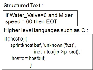
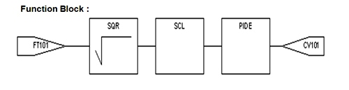
Other Programming Languages :
While ladder logic is the oldest and most popular language used in PLCs today, many other languages are gaining in popularity and are in wide use. Examples are :
• Sequential Function Chart(SFC).
• Function Block.
• Structured Text.
• Higher level languages such as C.

Architecture
Control System Architectures :
A complete control system is made up of a combination of PLCs, networks, I/O, terminals and software. All the components work together to form a complete control system.
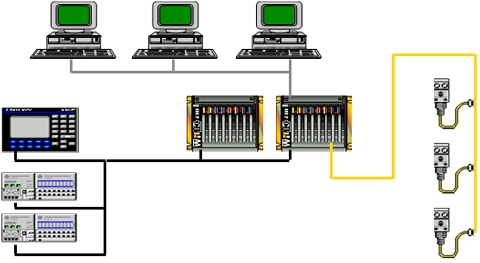
Within a control system architecture there are many subsystems and terms used to describe them. This section will go over some of the popularly used terms to describe parts of control systems.
• Local I/O
• Distributed I/O
• Centralized I/O
• Centralized Control
• Distributed Control
• Control System
• Data Acquisition System
• Safety System
I/O Systems :
I/O systems are often referred to as local or distributed :
• Local refers to the I/O being attached directly to the controller or on the same backplane as the Controller.
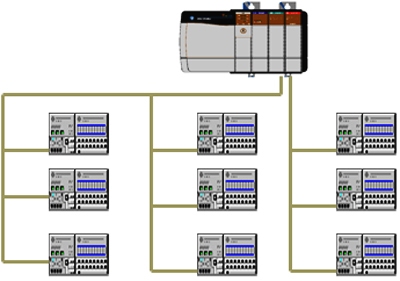
• Distributed refers to I/O which is not on the same backplane as the Controller. Distributed I/O is connected using a network.
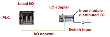
The distributed input module sends the inputs across the backplane to the adapter. The adapter sends them over the I/O network to the PLC (Controller).
I/O Architectures :
I/O architectures are made up of I/O systems. The architectures are referred to as Centralized and Distributed :
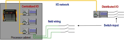
• Centralized refers to the I/O being located near or in the same cabinet as the processor. Wires from field devices are brought back to the I/O, and can be quite long.
• Distributed refers to I/O that is located near the field devices. The wires from the field devices are short. The network cable is run out to the Distributed I/O instead of running the field wires back to the I/O.
Systems Vs. Architectures :
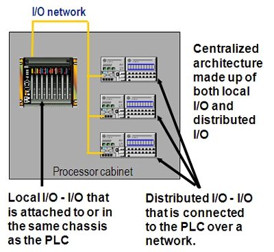
• I/O systems are part of an I/O architecture :
-> If all the I/O is located near or in the same cabinet as the processor, it is a centralized architecture. Within the centralized architecture could be either local or distributed I/O, or both.
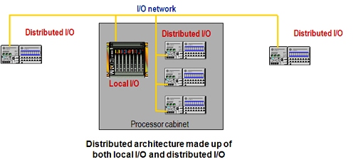
• I/O systems are part of an I/O architecture :
-> If some of the I/O is located remotely from the processor it is a distributed architecture. Within the distributed architecture is distributed I/O, or both local and distributed I/O.
Local vs. Distributed I/O System :
Why use Local I/O? :
• Faster than distributed I/O.
• Easy to install - add a module to the chassis : In some cases the I/O is already attached to the processor.
• Less expensive than adding distributed : Use the I/O on the processor or simply add a module to the backplane. Don’t need to add a chassis, power supply, etc.
Why use Distributed I/O? :
• Field devices distributed around the machine - too much wiring to take back to one chassis.
• Out of local I/O : local I/O limited by number of slots in the backplane or fixed I/O attached to the processor.
• Local I/O does not meet your needs module type, current capability, etc.
Centralized vs. Distributed I/O Architecture :
Why use a Centralized Architecture? :
• If using local only, then it is faster than distributed I/O.
• If the only centralized I/O is local I/O, then you don’t have to buy additional chassis, power supply, etc.
• The field devices are near the cabinet or processor so there is no wiring cost savings of going distributed.
Why use a Distributed Architecture? :
• Field devices distributed around the machine - too much wiring to take back to one chassis.
• I/O mounted to machine - becomes a part of it instead of in a central cabinet.
Centralized Control :
• Centralized control refers to a control system where a single (usually large) PLC controls all of the I/O and performs all the control for the system.

Advantages and disadvantages of centralized control :
Advantages :
- The control program is all in one place.
- Easier to troubleshoot system problems.
- I/O performance throughout entire system.
Disadvantages :
- Programs can get quite large.
- Related I/O performance slower compared to distributed control.
- Single PLC failure shuts down entire system.
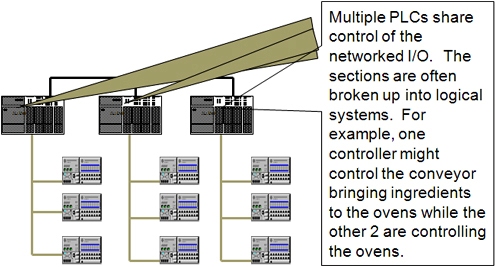
Distributed Control :
• Distributed control refers to a control system where multiple PLC controllers share the responsibility of controlling the system. The PLC’s usually communicate frequently with each other.
Advantages and disadvantages of distributed control :
Advantages :
- Segmented programs to specific tasks.
- Easier to troubleshoot local problems.
- Performance on local network.
Disadvantages :
- System problems harder to troubleshoot.
- Performance from I/O across PLC’s.
- Cost.
- Maintain multiple programs.

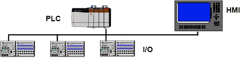
The Control System :
• The control system is the system that is responsible for the control of the process. This is the system that includes the PLC, all of the I/O and any Human Machine Interfaces (HMI).
Data Acquisition System :
• The Data Acquisition system is generally responsible for collecting data about the control system, and storing it on master computers or servers, or displaying it on terminals. The data is often used later for reporting or charting purposes.
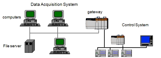
• Made up of devices and networks which are responsible for acquiring data about the process . Not responsible for direct control of the process.
• The network used for data acquisition is often Ethernet. While data acquisition devices can exist directly on the control network, a gateway is often used to separate network traffic between the data acquisition system and the control system.
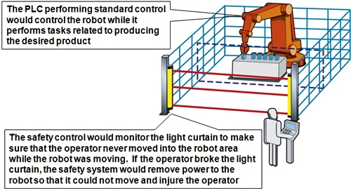
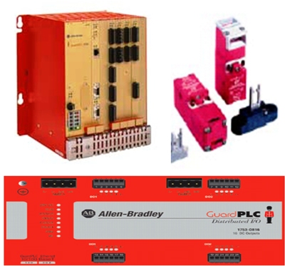
Safety System :
• The Function of a Safety System is to monitor and control conditions on a machine or process that are hazardous in themselves or, if no action were taken, may give rise to hazardous situations.
• The Safety System runs in parallel with the Control System. The Control System and Safety System may share components :
-> Focus of Control System is Throughput.
-> Focus of Safety System is Protection.
• A Safety system is designed to protect :
-> People.
-> Environment.
-> Machinery.
• The safety system is often referred to as ” safety control” while the PLC system controlling the devices that produce the end product is often referred to as the “ standard control”.