Industrial Process Control Loop
A control loop is the fundamental building block of industrial control systems. It consists of all the physical components and control functions necessary to automatically adjust the value of a measured process variable (PV) to equal the value of a desired set-point (SP). It includes the process sensor, the controller function, and the final control element (FCE) which are all required for automatic control.
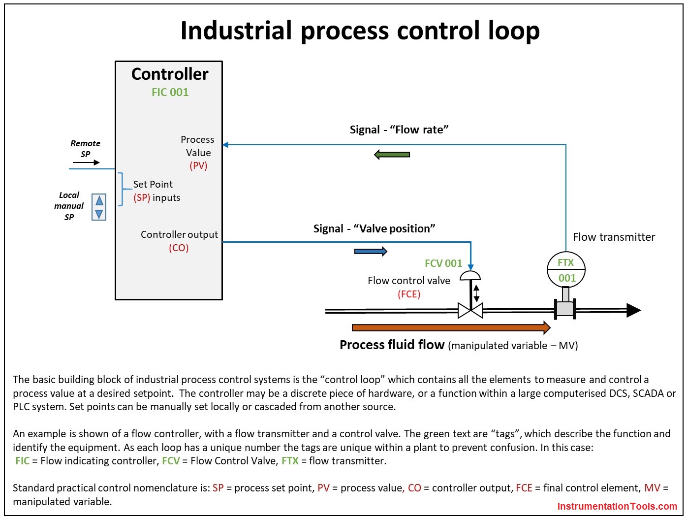
The accompanying diagram shows a control loop with a single PV input, a control function, and the control output (CO) which modulates the action of the final control element (FCE) to alter the value of the manipulated variable (MV). In this example, a flow control loop is shown, but can be level, temperature, or any one of many process parameters which need to be controlled. The control function shown is an “intermediate type” such as a PID controller which means it can generate a full range of output signals anywhere between 0-100%, rather than just an on/off signal.
In this example the value of the PV is always the same as the MV, as they are in series in the pipeline. However, if the feed from the valve was to a tank, and the controller function was to control level using the fill valve, the PV would be the tank level, and the MV would be the flow to the tank.
The controller function can be a discrete controller, or a function block in a computerised control system such as a distributed control system or a programmable logic controller. In all cases, a control loop diagram is a very convenient and useful way of representing the control function and its interaction with plant. In practice at a process control level, the control loops are normally abbreviated using standard symbols in a Piping and instrumentation diagram, which shows all elements of the process measurement and control based on a process flow diagram.