This post regarding instrument index field configuration can be a supplement to Intools tutorial. In Intools instrument index module, there should be one main view which shows major fields pertaining to the tag number.
This main Intools Instrument Index view should consists of but not limited to Tag No, instrument type description, Loop No, service description, P&ID No, line/vessel No, location, I/O type, control system, maximum calibrated range value, minimum calibrated range value, set point, engineering units, manufacturer, model number and applicable reference document. This main view will be used for editing the tag number details.
In Intools, fields which will be shown in instrument index can be configured under browser module. The configuration should be set in the beginning of the project. However, new field can be added anytime in the middle of the project.
InTools Tutorial - Instrument Index
The following is the step-by-step instruction how to create/set Intools instrument index view:
-
Open Instrument Index Browser
-
Expand “Instrument Index” Folder
-
Expand “Instrument Index Standard Browser”
-
Expand “Default View”
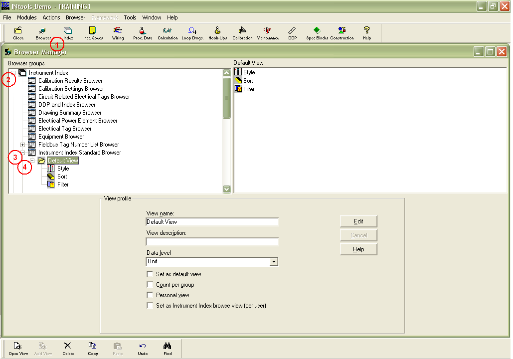
DEFAULT VIEW which has already been exist can be used…
-
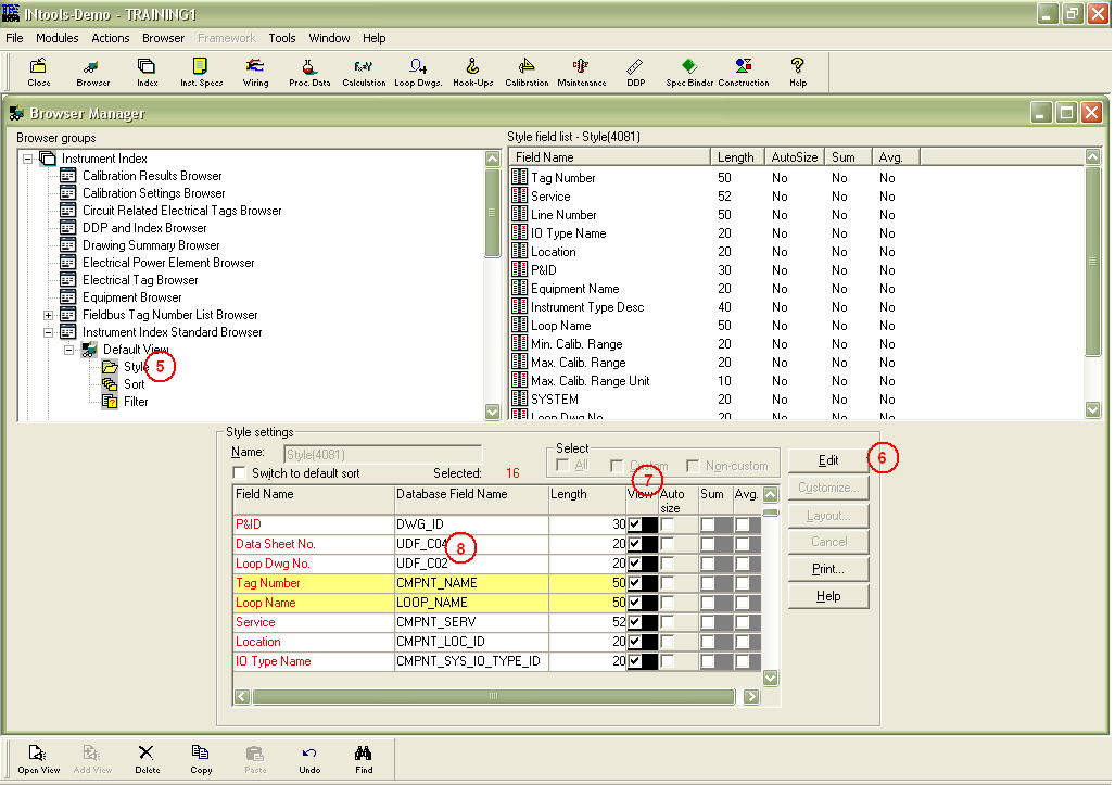
Select “Style” under Default View
-
Click “Edit”
-
Check the box under column view for field which will be shown on instrument index view.
-
There are spare fields named UDF_CXX which can be used as custom field such as applicable reference document (layout drawing number, etc), remarks, etc if necessary.
-
Save
The next step is of course populating the data base with tag numbers and its details through instrument index module.
If this main Intools instrument index view has been established, it would be easier to generate other documents such as I/O list, Procurement List, etc by creating a new style and performing filtering and adding more field which specifically related to the documents.