The hydramatic Division of the General Motors Corporation specified the design criteria for the first programmable controller come in 1968.
Programmable logic controllers, also called programmable controllers or PLCs, are solid-state members of the computer family, using integrated circuits instead of electromechanical devices to implement control functions.
They are capable of storing instructions, such as sequencing, timing, counting, arithmetic, data manipulation, and communication, to control industrial machines and processes.
Purposes - Initially designed to replace relay logic boards, Sequence device actuation, Coordinate activities accepts input from a series of switches, Sends output to devices or relays
What is PLC?
Programmable Logic Controller (PLC) is a digital computer used for the automation of various electro-mechanical processes in industries. These controllers are specially designed to survive in harsh situations and shielded from heat, cold, dust, and moisture etc.
PLC consists of a microprocessor which is programmed using the computer language. The program is written on a computer and is downloaded to the PLC via cable. These loaded programs are stored in non – volatile memory of the PLC.
During the transition of relay control panels to PLC, the hard wired relay logic was exchanged for the program fed by the user.
A visual programming language known as the Ladder Logic was created to program the PLC.
Building blocks of PLC
Functions of various blocks in PLC
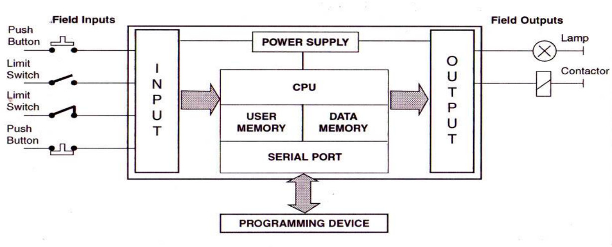
PLCs have input/output devices like switches, push buttons, limit switches,sensors,lamp indicators,relays solenoids motors etc. block diagram of a PLC shown in above Fig. It has three major units/sections.
• I/O (Input/Output) Modules.
• CPU (Central Processing Units).
• Programmer/Monitor
The input section converts the field signals supplied by input devices/sensors to logic-level signals that the PLC’s CPU can read.
The Processor Section reads these inputs, Processes the signal, and prepares the output signals.
The output section converts the logic level output signals coming from processor section to high level signals and used to actuate various output field devices.
The programmer/monitor is used to enter the user’s program into memory and to monitor the execution of the program.
I/O Section
The I/O section establishes the interfacing between physical devices in the real world outside the PLC and the digital arena inside the PLC.
The input module has bank of terminals for physically connecting input devices, like push buttons, limit switches etc. to a PLC.
The role of an input module is to translate signals from input devices into a form that the PLC’s CPU can understand.
The Output module also has bank of terminals that physically connect output devices like solenoids, motor starters, indicating lamps etc. to a PLC.
The role of an output module is to translate signals from the PLC’s CPU into a form that the output device can use.
The tasks of the I/O section can be classified as:
• Conditioning
• Isolation
• Termination
• Indication
An electronic system for connecting I/O modules to remotely located I/O devices can be added if needed. The actual operating process under PLC Control can be thousands of feet from the CPU and its I/O modules
CPU Section
The Central Processing Unit, the brain of the system is the control portion of the PLC.
It has three Subparts.
• Memory System
• Processor
• Power Supply
Memory System
The memory is the area of the CPU in which data and information is stored and retrieved.
The total memory area can be subdivided into the following four Sections.
I/O Image Memory
The input image memory consists of memory locations used to hold the ON or OFF states of each input field devices, in the input status file.
The output status file consists of memory locations that stores the ON or OFF states of hardware output devices in the field.
Data is stored in the output status file as a result of solving user program and is waiting to be transferred to the output module’s switching device.
Data Memory
It is used to store numerical data required in math calculation, bar code data etc.
User Memory
It contains user’s application program.
Executive Memory
It is used to store an executive program or system software. An operating system of the PLC is a special program that controls the action of CPU and consequently the execution of the user’s program.
A PLC operating system s designed to scan image memory, interprets the instruction of user’s program stored in main memory, and executes the user’s application program the operating system is supplied by the PLC manufacturer and is permanently held in memory.
Processor
The processor, the heart of CPU is the computerized part of the CPU in the form of Microprocessor / Micro controller chip.
It supervises all operation in the system and performs all tasks necessary to fulfill the PLC function
- It reads the information i.e. status of externally connected input devices with input module.
- It stores this information in memory for later use.
- It carries out mathematical and logic operations as specified in application program.
- After solving the user’s program, it writes the result values in the memory.
- It sends data out to external devices like output module, so as to actuate field hardware.
- It performs peripheral and external device communication.
Power Supply
- The power supply provides power to memory system, processor and I/O Modules.
- It converts the higher level AC line Voltage to various operational DC values.
- For electronic circuitry.
- It filters and regulates the DC voltages to ensure proper computer operations.
Programmer/Monitor
The Programmer/Monitor (PM) is a device used to communicate with the circuits of the PLC. The programming unit allows the engineer/technicians to enter the edit the program to be executed.
In its simplest form it can be hand-held device with membrane keypad for program entry and a display device (LED or LCD) for viewing program steps of functions.
More advanced systems employ a separate industrial terminal or personal computers with type-writer type keyboard and CRT monitors. With the help of proprietary software, it allows programmer to write, view and edit the program and download it into the PLC.
It also allows user to monitor the PLC as it is running the program. With this monitoring systems, such things as internal coils, registers, timers and other items not visible externally can be monitored to determine proper operation.
Also, internal register data can be altered, if required. to fine tune program operation while debugging. Communication between PM and PLC is done via a cable connected to a special programming port on PLC.
Connection to the personal computer can be through a serial port or from a dedicated card installed in the computer
PLC Programming language
Using flowcharts, Using ladder logic and Using statement logics or mnemonics
PLC manufacturer
- Allen Bradley,
- Rockwell Automation,
- Mitsubishi,
- Omron,
- Siemens etc
Source: gpmeham.edu.in