I have used 12C x 1.5 mm2 Armoured for Solenoid valve( 240 VAC, 50 Hz) operation at 1 km from PLC. when power supply is off, I found from 60 to 110Vac in valve control wires,
Voltage is showing is in other core also around 190 V even after disconnection of power supply. Is there any solution to avoid induced voltage without changing the cable.
For your information these situation has serious impact in valve functionality, it become only opening when sending open or close signal command from PLC
Could any one help in order to eliminate the induced voltage?
well, the following procedure is not usual way, but sharing for your information -
FIRST METHOD
You can install a Local Relay Module and connect PLC output to this Relay Module. Connect 240V Ac power supply to the relay and power the Valves with this intermediate relay module.
To work this out, first check whether PLC output power able to switch ON and switch OFF the relay module.
In First Method we are using PLC power to energize and de-energize the relay module. as you have more induction voltage in cable, so first check whether you are able to make relay ON & OFF from PLC.
SECOND METHOD -
Instead of sending 240V AC power from the PLC, change the loop to DRY i.e. only continuity, when PLC sends signal say the output contact is NC contact and no signal then NO contact in the PLC
Now install Intermediate Relay Module at the Valve (field). Use the NO & NC signals from PLC to control this Relay module with auxiliary/external control power supply.
Now use 240V AC power supply and wire the Valves via this Intermediate Relay Module at the Field.
In Second method, we are using PLC output either NO or NC only. There will be NO 240V Ac output from PLC, you have to make wiring change in PLC.
Note : You can use single 240V AC power supply for Valve’s powering and for relay control supply. OR. use different power supplies, as per your availability. In my view, different power supplies will be good.
THIRD METHOD
If possible you can change the Junction box where some spares available in main cable. you have to lay branch cables from valve to that junction box.
YOU CAN CONNECT A SNUBBER CIRCUIT OR RC-CIRCUIT ACROSS RELAY TERMINALS TO REDUCE THE INDUCTION VOLTAGE IMPACT FOR ANY OF THE METHOD
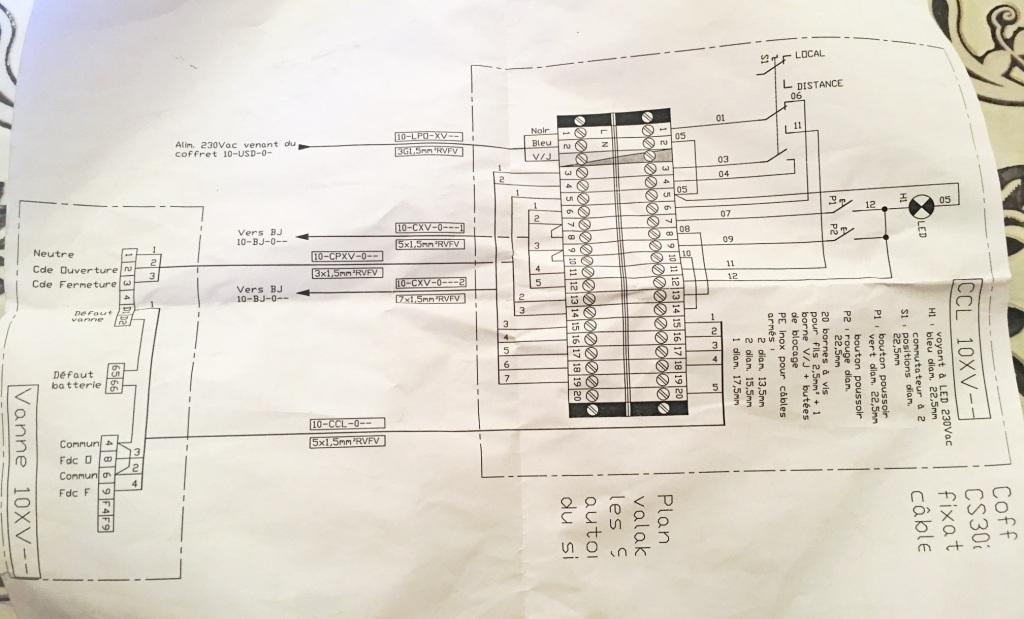
the power supply is feeded from PLC going to local distribution panel, from that panel we can energize each single local control station of valve with 220 Vac.
in the valve side we have 03 wires which are giving :
1- Commun is the phase
2- Opening command: when sending open command from PLC the valve start opening
3- Closing command when sending closing command from PLC the valve continue to open.
without sending any command of opening when i checked the voltage between opening and phase I have from 60 to 110Vac,
I have to note also that in the local distribution panel, each valve is feeded from seperate breaker, when I start to turn it on, the voltage in X valve start to raise influenced by Y, Z valves
1 PLC to Local Control Panel
2. Local Control Panel to Valves
Disconnect PLC wires in local control panel, connect another 240V AC and check the valves open/close from local control panel. if valves operation fine then the issue in between PLC to Local Control Panel.
As Issue in between PLC to Local Control Panel then you can try above mentioned first or second methods.
Second method will give 100% output as we use PLC NO or NC Contacts only.
Note : when PLC powers the Local control panel/valves then we don’t say that it is dry contact. we loop 240V Ac power in the relay output.
Actually the main problem is the induced voltage in DO control wires which are connected between the PLC & JB " it change between 60 to 100V’’, same thing for spare wires else if they are disconnected from the both side there is voltage.
the power supply is provided from different source as I mentioned previously, which connected directly to valve control panel.
What I am trying to explain is else if the power supply is off, I still get the induced voltage.
What is the best solution in order to solve the problem, knowing that the cable lenght between PLC & field installation is over than 1000M.
I could provide interconnection drawing for the installation if you need.