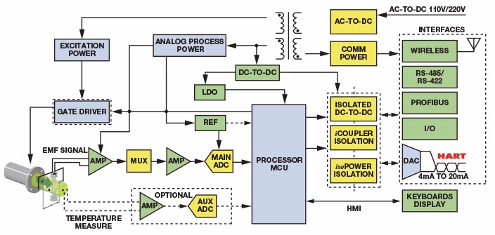
Magnetic Flow meter Circuit Diagram
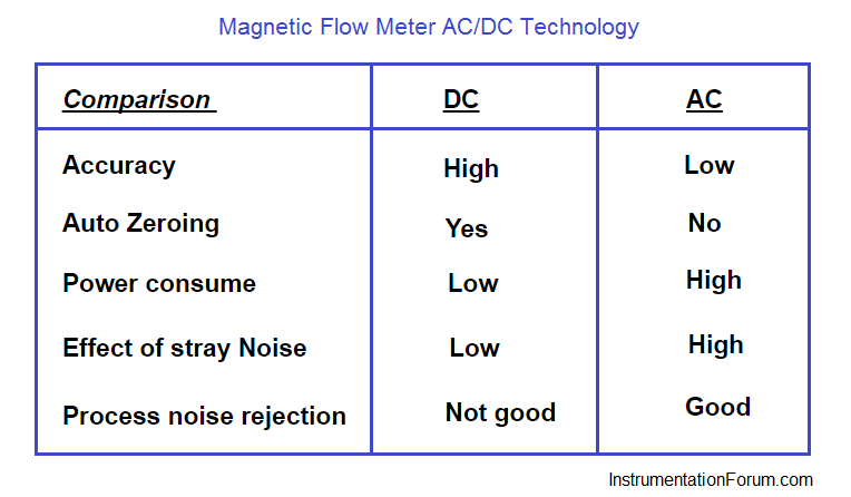
• AC type magnetic flow meters apply line voltage to the magnetic coils. The signal generated is a low level AC signal in the high microvolt to low mV range.
• In the pulsed DC type Magnetic flowmeter, the magnet coils are periodically energized. DC excitation may be either on-off or plus-minus excitation. The principle is to take a measurement of the induced voltage when the coils are not energized and to take a second measurement when the coils are energized and the magnetic field has stabilized.
•In all the pulsed DC approaches, the concept is to take a measurement when the coils are excited and store that information, then take a second measurement of the induced voltage when the coils are not excited. The voltage induced is a combination of both noise and signal when the coils are energized and it is only noise when the coils are de-energized. Subtracting one from the other will yield only signal.
Magnetic Flow Meter AC/DC Technology
•Design Temperature Upto 120 °C with Teflon liners; Upto 180 °C with Ceramic liners.
•Type of flow detected Volumetric flow of conductive liquids, including slurries of corrosive or abrasive materials.
•Flow Ranges 0.01 to 100000 GPM (0.04 to 378000 l/m)
•Size Ranges From 0.1 to 96” in diameter
•Accuracy ±1% of full scale for AC excitation.
±1% of actual flow for 10:1 range and ±0.5% of actual flow for 2:1 or 5:1 range.’