The term Modem Definition is an acronym for modulator-demodulator. The primary modem function is to convert digital data into an analog form which is suitable for transmission on common carrier circuits (example telephone lines). Modulation is the D/A conversion in which the digital data is placed on the transmission line by modulation of a tone or carrier. Demodulation is the reverse process.
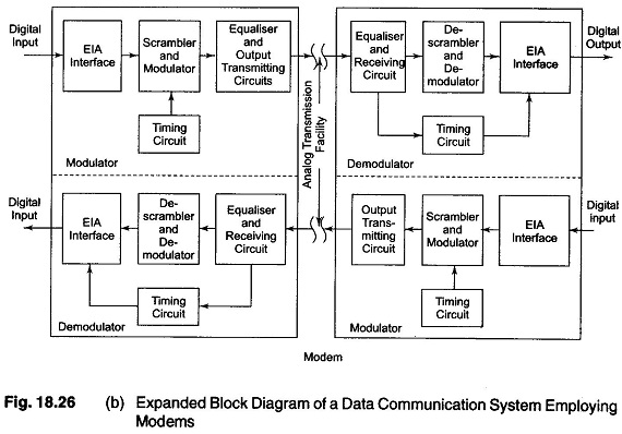
In a data communication system, transmitting and receiving modems are necessary at each end of the analog transmission line. The interfaces in the modulator and demodulator sections are usually EIA RS 232 C or current loop interfaces providing connections for standard external devices. The output transmitting circuits and receiving circuits are networks required for transmitting and receiving analog information to and from the transmission line.
Three modulation techniques in common use are amplitude, frequency and phase modulation. In a simple amplitude modulation system, the amplitude of the modulated carrier frequency corresponds to the value of the data bits. The spectrum of the modulated waveform includes the carrier frequency plus the upper and lower side bands. The side bands are displaced from the carrier by the frequency of the modulating input. The resulting band width is therefore twice that of the data rate.
In a frequency modulation system, digital signals are connected to one of the two frequencies corresponding to the 0 and 1 values of the data. Modulation of this form is known as Frequency Shift Keying (FSK). FSK is a commonly used technique for low speed transmission (typically 0 to 600 bits/s).
Modems operate with one functioning as an originate unit and the other as an answer unit. The originate modem transmits on a low frequency channel, using 1.270 kHz for a mark and 1.070 kHz for a space. It receives on a high frequency channel using 2.225 and 2.025 kHz respectively for mark and space. The answer Modem Definition transmits on the high frequency channel and receives on the lower. These frequencies are industry standards and assure compatibility with most commercially available low speed data channels, including national time sharing services. The carrier frequencies occupy discrete portions of the pass band. However, the frequency modulation generates side bands whose deviation from the carrier is directly dependent on the transmission bit rate. The total required band width therefore depends on the transmission speed.
Phase modulation is widely utilized in high speed systems. In its simplest form, two carriers which have identical frequencies but are 180° out of phase with one another are used.
Each phase is used to represent a mark or space condition. In such a system, both phase angles are referenced to a defined phase angle that is known by the transmitter and receiver. Another method transmits information contained in the relationship of the two successive phase angles, known as differentially coherent phase shift keying (PS K). PSK eliminates the need for a stable phase reference at the receiver.
The transmission timing for the digital data exchange rate can be either asynchronous or synchronous. Asynchronous timing is simpler and less expensive, but has the disadvantage of a lower data exchange efficiency. Start and stop bits are used for each character, which may account for nearly 30% of the transmission time. In operation, the start bit is recognized by the receiver and the succeeding bits are received at a specified rate. The stop bit(s) permits the receiver to reset and prepare for the next start bit. Low speed data systems employing devices such as teletypewriters often operate in this fashion.
The greater complexity and cost of synchronous modems over asynchronous units is due to the circuitry necessary to derive the timing from the incoming data and to pack more than one bit into one baud (the number of signaling elements per unit time).
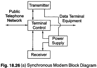
Synchronous modems typically consist of four sections, as shown in Fig. 18.26(a). The transmitter, receiver, terminal control and power supply. The transmitter section of a synchronous modem typically consists of timing (clock), scrambler, modulator, digital to analog converter and equalizer circuits. The expanded block diagram is shown in Fig. 18.26(b). The timing circuit provides the basic clocking information for both the modem and the data terminal equipment (DTE) that is providing the data to be transmitted. The internal timing is usually controlled by a crystal oscillator to within about 0.05% of the nominal value.
Since the receiver clock is derived from the received data, those data must contain enough changes from 0 to 1 (and vice versa) to assure that the timing recovery circuit stays in synchronization. In principle, the data stream provided by the associated terminal or business machine can consist of any arbitrary bit pattern. If the pattern contains long strings of the same value, the data will not provide the receiver with enough transitions for synchronization. The transmitter must prevent this condition by changing the input bit stream in a controlled way. The part of the transmitter circuitry that does this is called the scrambler. Scrambler are usually implemented as feedback shift registers which may be cascaded or connected in series. They are designed to ensure that each possible value of phase angle is equally likely to occur, to provide the receiver demodulator with enough phase shifts to recover the clocking signal. Although scrambling is necessary for the reasons cited above, it increases the error rate, since an error in one bit is likely to cause an error in subsequent bits. To counteract this, some modems encode the input to the scrambler in gray code, so that the most likely error in demodulation will cause only a 1 bit error when decoded at the receiver.
The modulator section of the transmitter converts the bit patterns produced by the scrambling process into an analog signal representing the desired phase and amplitude of the carrier signal. The carrier frequency, baud rate, and number of bits represented by each baud is different for modems of different rates. The modulator collects the correct number of bits and translates it into a number giving the amplitude of the electrical signal that is correct for the carrier frequency and phase of the carrier at that instant in time. Modulation differs for Modem Definition of different speeds, and those made by, from different manufacturers.
The equalizer section of the transmitter is relatively simple, since it can compensate only for the average of expected errors on the output channel. The receiver equalizer, however, must compensate for the actual errors introduced in the transmission path. This is done by using adaptive equalizers which measure errors observed in the received signals and adjusts some parameter of the circuit (usually the receiver clock frequency) to track slowly varying changes in the condition of the transmission line.
At the receiver, the incoming signal from the line is modulated or frequency translated using an internal clock. The resulting intermediate frequency is processed to produce a clock signal at the rate at which the data is actually being received. This signal is applied as the reference to a phase locked loop oscillator. The output of this oscillator is a stable signal locked to the incoming line frequency in both phase and frequency.
The descrambler section of the receiver performs an operation that is the inverse of the scrambler.
Synchronous timing is used in higher speed data systems. The transmitter and receiver are timed from synchronized clocks. A synchronized preamble code is transmitted first. The code is followed by the information to be transmitted, without start or stop bits. The receiving modem maintains synchronism by sampling the received bits. Elimination of the start/stop bits substantially increases the throughput of the synchronous system.
Modems operate in both half and full duplex modes. Since full duplex operation allows simultaneous transmission and reception, two transmission lines are required.
The public telephone network is the most commonly used transmission system. Dial-up lines having bandwidths of 3 kHz may be used for transmission rates of up to 4800 bits per second, whereas lines used for high speed transmission must be leased.