An opto-isolator, also known as an optocoupler, is an electronic component that provides electrical isolation between two circuits by using light to transmit signals.
The principle of operation of an opto-isolator involves the following steps:
Components
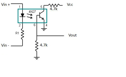
An opto-isolator consists of an input section and an output section. The input section typically comprises an LED (Light-Emitting Diode), while the output section contains a photosensitive device, such as a phototransistor or a photoresistor.
Input Circuit
The input circuit of the opto-isolator is connected to the control circuit or source that needs to be isolated. When an electrical signal is applied to the input circuit, it energizes the LED. The input circuit can be a low-voltage, low-current signal, making it compatible with sensitive electronic components.
Light Emission
As the LED is energized, it emits light, typically in the infrared spectrum. The emitted light intensity is directly proportional to the input current flowing through the LED.
Optical Coupling
The emitted light from the LED enters the output section of the opto-isolator, which contains the photosensitive device. The photosensitive device, such as a phototransistor, is designed to detect and respond to the incoming light.
Electrical Isolation
When the incoming light falls on the photosensitive device, it induces a corresponding electrical response. The response can be a change in resistance, voltage, or current, depending on the type of photosensitive device used.
Output Circuit
The electrical response from the photosensitive device is utilized in the output circuit of the opto-isolator. This output circuit can be connected to the isolated circuit, which is kept separate from the input circuit.
Isolation Benefits
The opto-isolator effectively isolates the input circuit from the output circuit, preventing the transfer of electrical noise, voltage spikes, or potential ground loops. It also provides protection against voltage differences and enhances safety in applications where isolation is crucial, such as high-voltage systems or situations where there is a need for isolation between sensitive control circuits.
The principle of an opto-isolator relies on the fact that light can be used to transmit signals across an isolation barrier, allowing communication between two circuits while maintaining electrical separation. This feature makes opto-isolators widely used in various applications, including power electronics, industrial control systems, telecommunications, medical devices, and more.