P&ID is the acronym for “Piping and instrumentation diagram”. A P&ID is a very detailed diagram showing the processes happening within a plant, the involved equipment, and their interconnections.
P&ID SYMBOLS
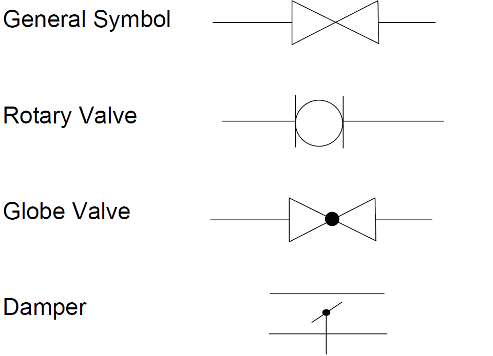
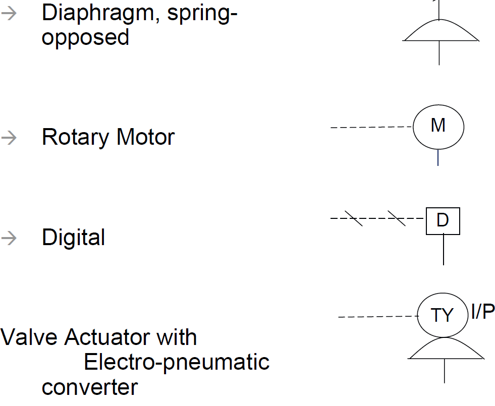
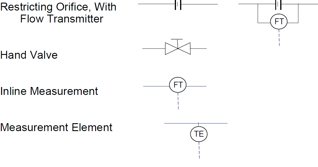
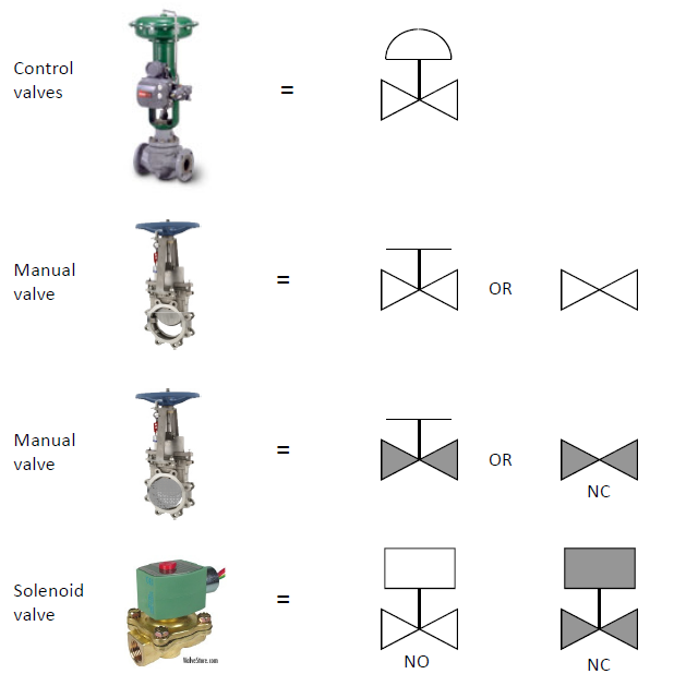
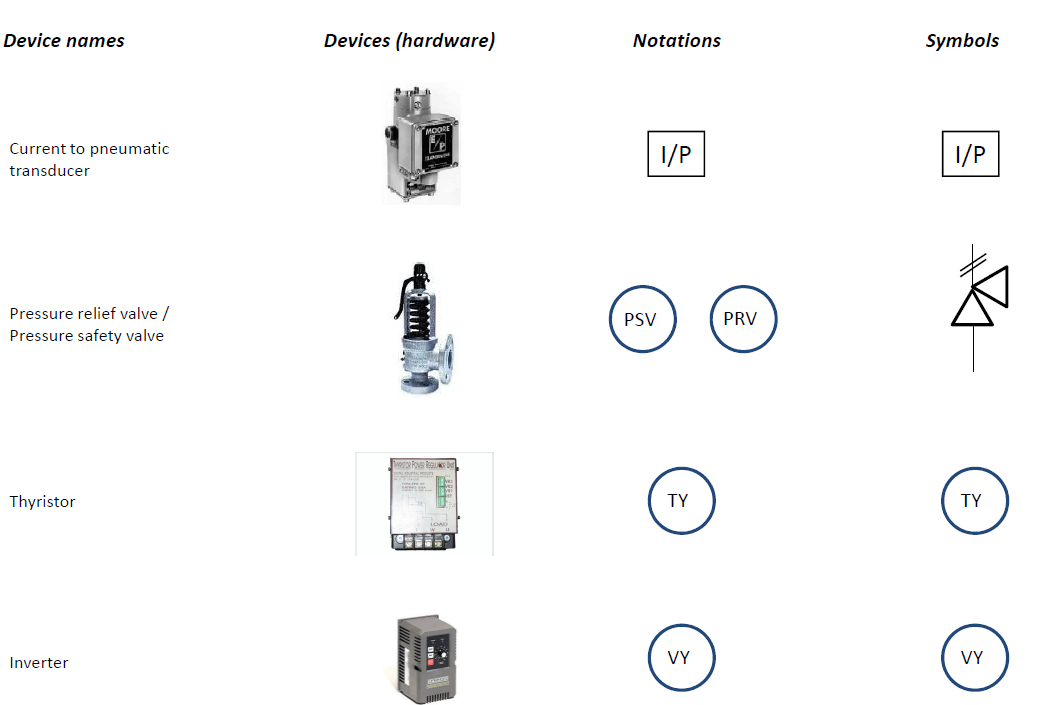
A set of (somehow) standardized P&ID symbols is used by process engineers to draft such diagram. P&ID symbols exist for all major components and lines, such as valves, vessels, instruments, pumps, compressors, and towers.**
P&ID ABBREVIATION AND IDENTIFICATION
Abbreviation is used to define:
An equipment to specify its type or service.
Example: For a Pump generally ’AP’ abbreviation is used for numbering. AP1002, AP6009 etc.
Example: For a Vacuum Pump generally ’AV’ abbreviation is used for numbering. AV1012, AP4007 etc.
Example: For a storage tank ‘ST’ and for vessel ‘AB’ is used for numbering.
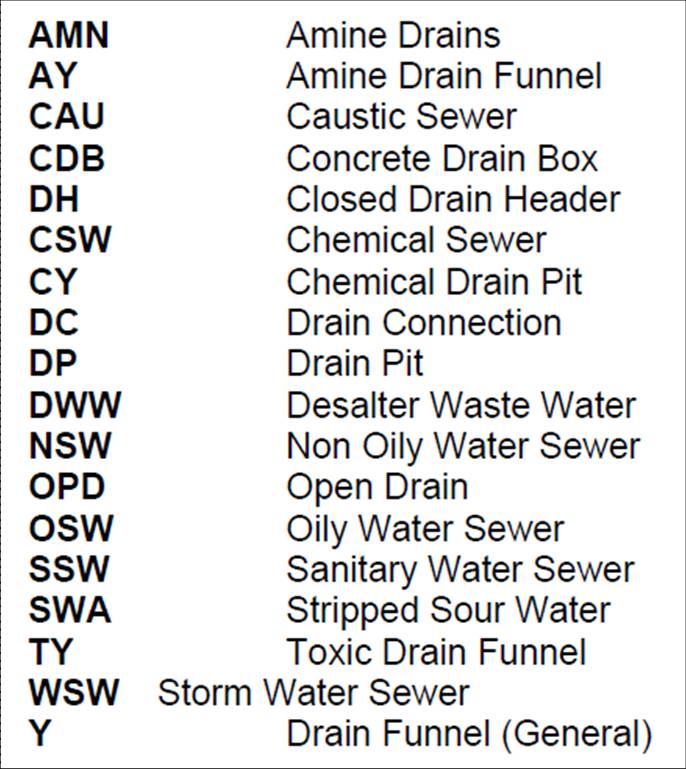
A pipe line to specify its service.
Example: ‘CWR’ is used for the Cooling Water Supply line.
Example: ‘HOS’ used for Hot Oil Supply line.
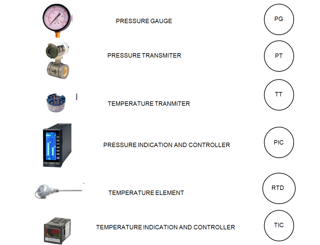
An Instrument to define its function.
Example: ‘PRV’ used for control valve to Control Pressure.
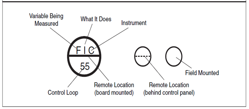
Example: ‘FIC’ used for Instrument which is used to Indicate and Control Flow.
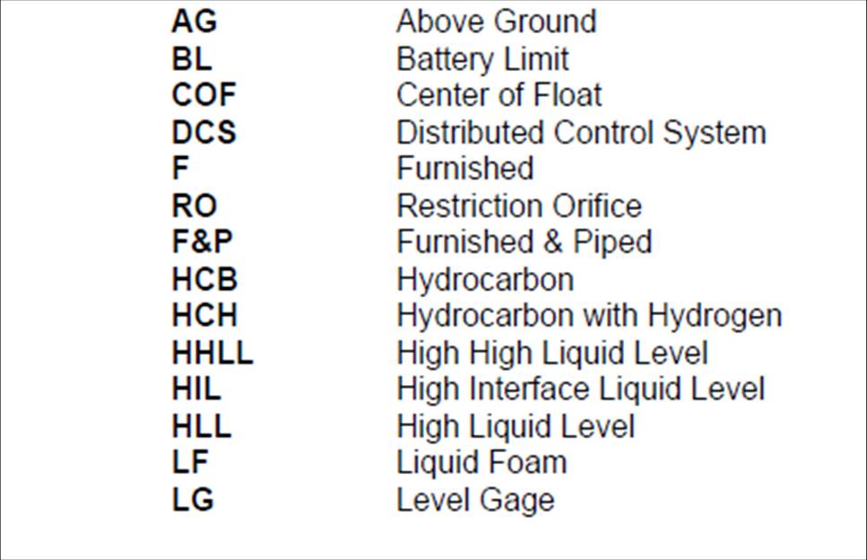
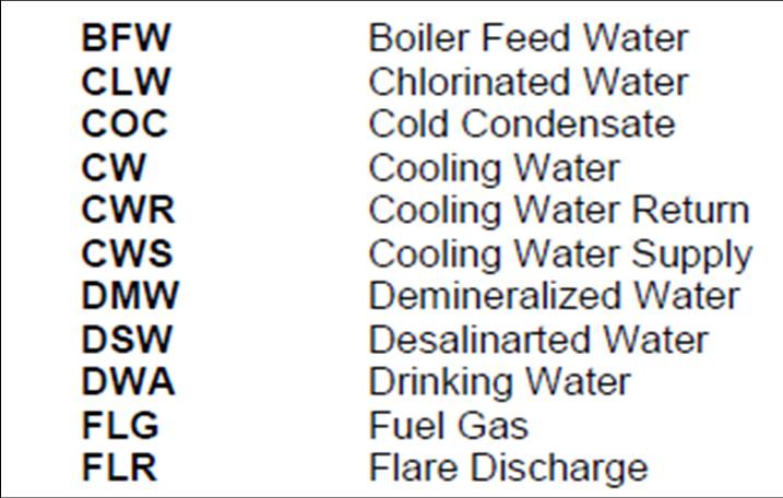
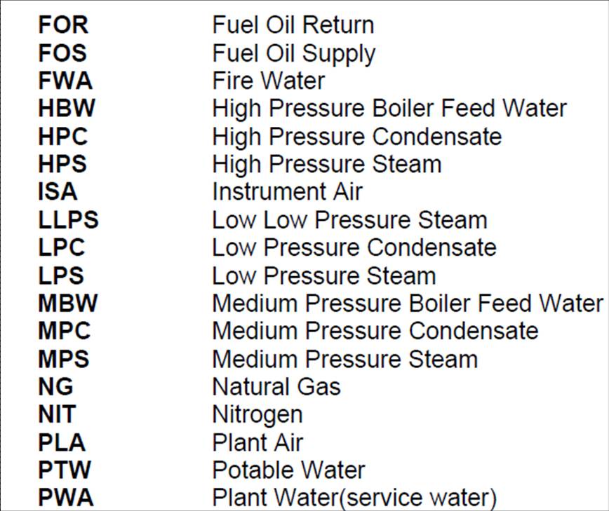
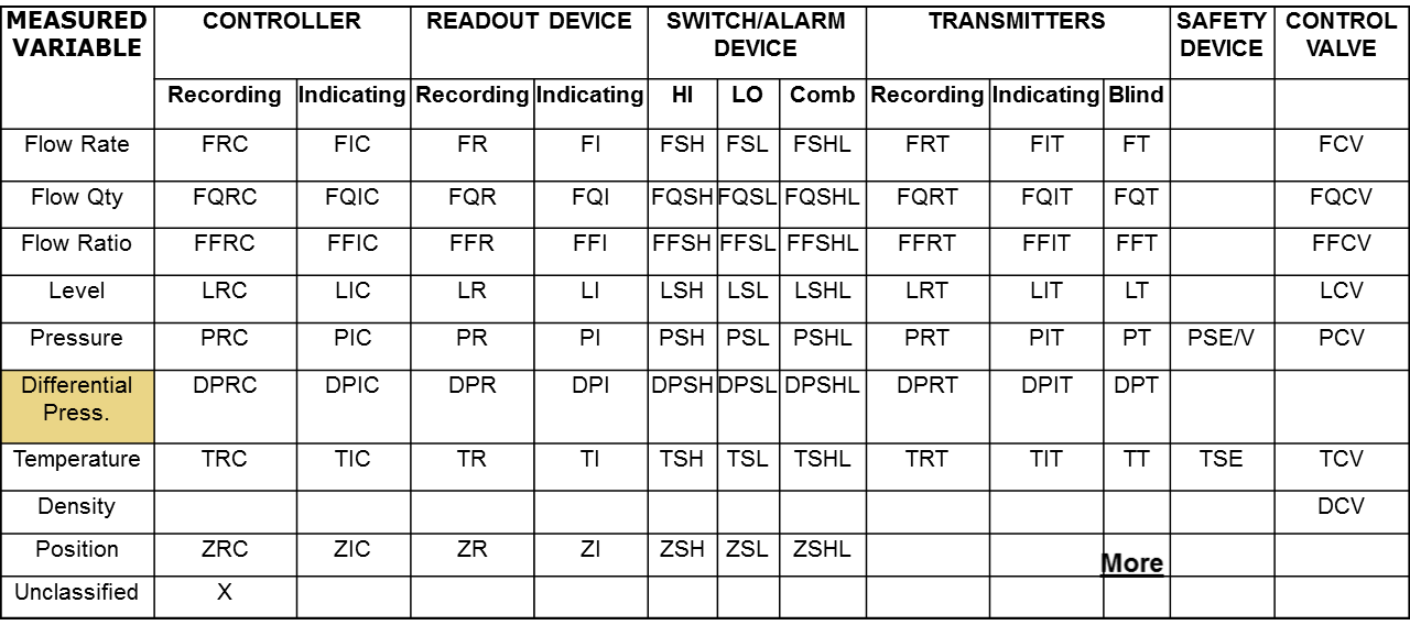
Bellow is list of some abbreviation generally used in a standard P&ID:
Letter is used to classify the instrument by it’s function and number is used to identify the loop/interlock. Identification letters on the ISA symbols indicate:
The variable being measured (e.g. flow, pressure, temperature).
The device’s function (e.g., transmitter, switch, valve, sensor, indicator).
Some modifiers (e.g., high, low, multifunction).
In the instrument tag number in above figure the initial letter indicates the measured variable. The second letter indicates a modifier, readout, or device function. The third letter usually indicates either a device function or a modifier.
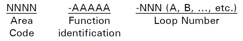
In that cases where the instrument is considered to be identified by it’s location/area then the instrument tag number format will be as bellow:
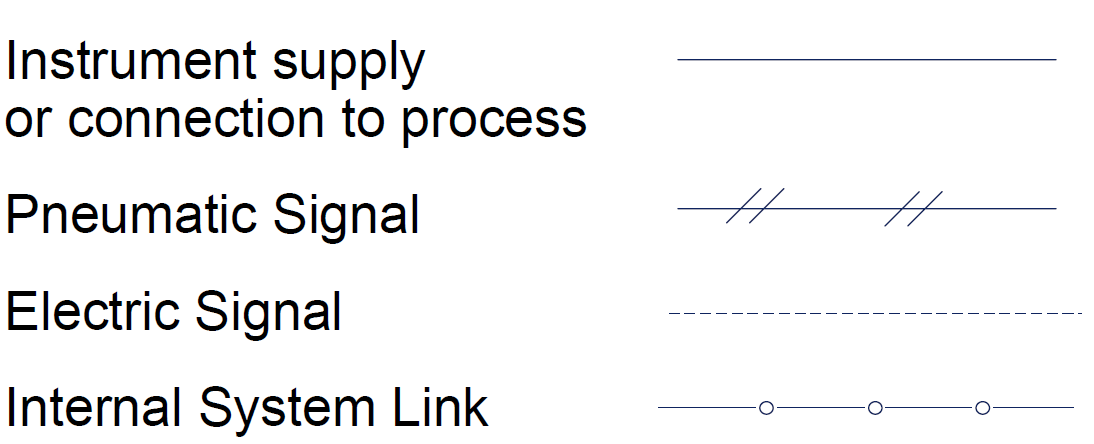
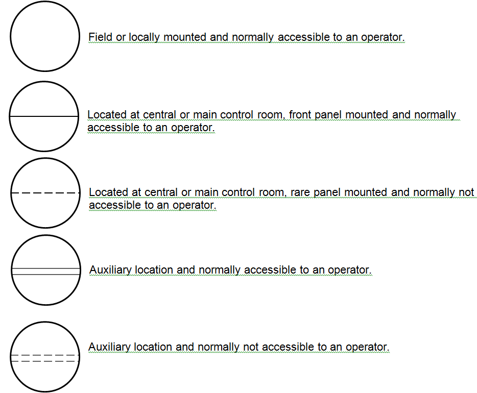
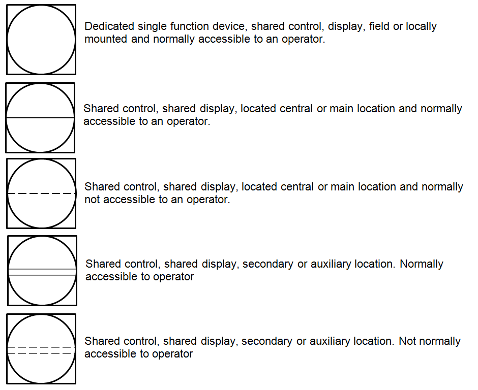
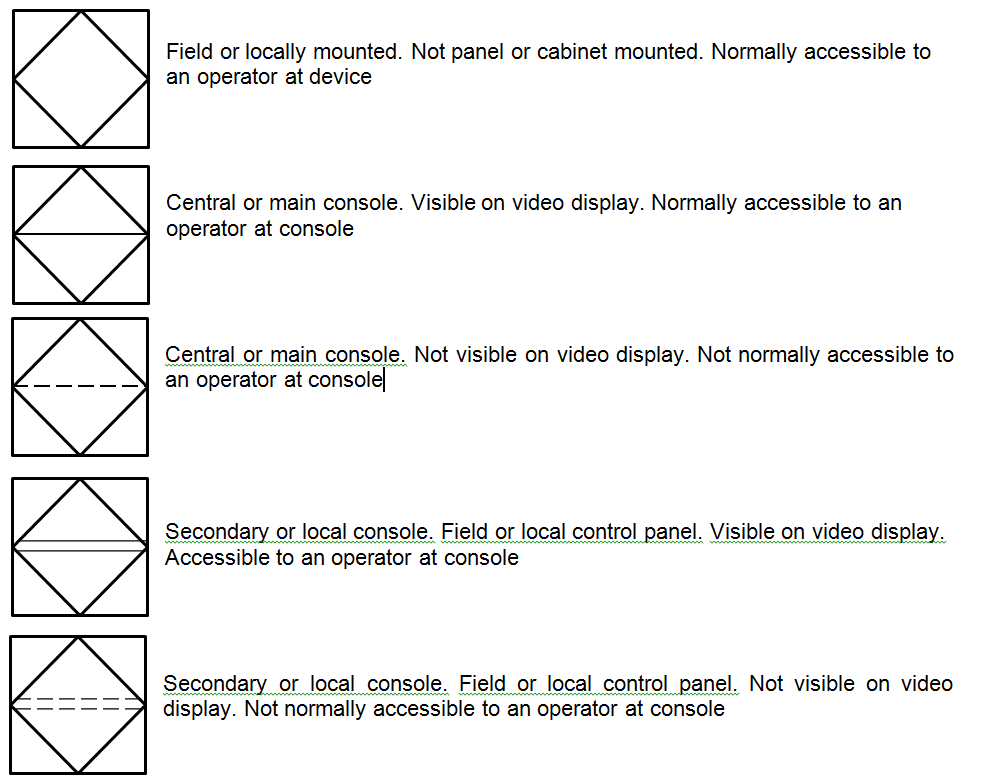
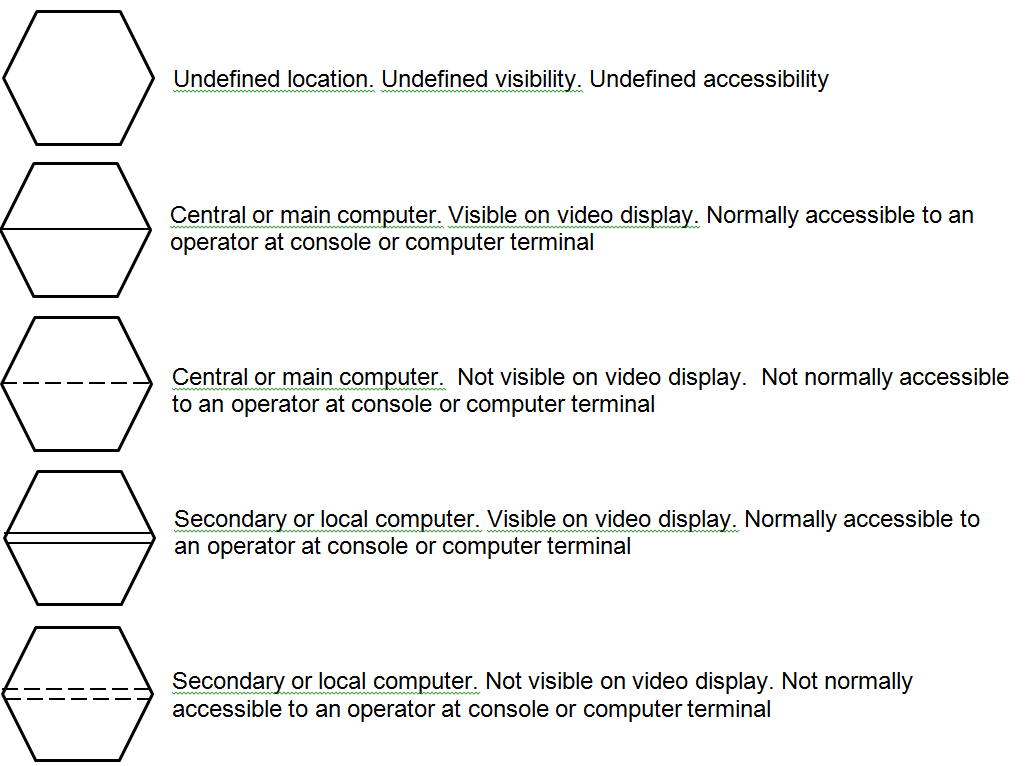
Shape like circles, squares, diamonds, hexagons, and lines used to represent the hardware and software instruments and functions as follows:
Discrete Devices and Functions, represents discrete hardware instruments and functions that are implemented in non-microprocessor-based systems similar to single-case transmitters, controllers, indicators etc.
Shared Devices and Functions, represents shared and distributed software analog instruments and functions that are implemented in microprocessor-based systems similar to distributed control or programmable logic control systems.
Shared On–Off Devices and Functions, represents shared and distributed on–off software instruments and functions that are implemented in microprocessor-based control systems similar or equal to a distributed control or programmable logic control systems.
Computer Devices and Functions, represents shared and distributed on–off software instruments and functions that are implemented in a computer-based control system