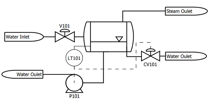
The PFD is a purely conceptual document. It only has the minimum information relating to the specifics of the piping or instrumentation of a system. The P&ID shows the engineering details of the equipment, instruments, piping, valves and fittings and their arrangement. It is often called the Engineer Flow sheet or Engineering Line Diagram.
P&IDs are produced and revised over many years by different people to reflect process improvements and additions, as well as changing control technology.
Even symbolism may change, for example, the original publication standard ANSI/ISA-5.1-2009 is used worldwide but only as a reference for instrument symbolism in site standards.
The information included also depends on the design office customs and practices and could have very detailed information on the following items:
- Equipment;
- Pipes;
- Valves;
- Ancillary fittings;
- Pumps;
- Control loops.
The P&ID diagram should resemble the process flow sheet, but the process information is not shown. Each item shown on the P&ID is given a unique identification number called a P&ID tag, which allows the item to be tracked throughout the design.
P&IDs are developed in steps. First the major equipment is drawn; afterwards all the instrumentation and control equipment is added, often requiring additional space.
Also, P&IDs are controlled documents: control means that there should be verification checking or some other quality assurance procedure to show that P&IDs carry the definitive information from which many design entities draw their work.
An example, using the flasher level control described in the previous section, is shown in Figure.
