• Process flow diagrams (PFDs) are used in chemical and process engineering. These diagrams show the flow of chemicals and the equipment involved in the process. Generally, a Process Flow Diagram shows only the major equipment and doesn’t show details. PFDs are used for visitor information and new employee training.
• A Process and Instrument Drawing (P&ID) includes more details than a PFD. It includes major and minor flows, control loops and instrumentation. P&ID is sometimes referred to as a Piping and Instrumentation Drawing. These diagrams are also called flowsheets. P&IDs are used by process technicians and instrument and electrical, mechanical, safety, and engineering personnel.
• Piping and instrumentation diagram (P&ID): A diagram which shows the interconnection of process equipment and the instrumentation used to control the process.
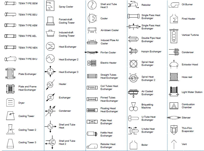
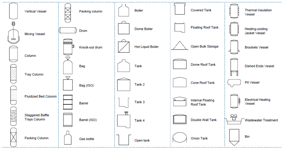
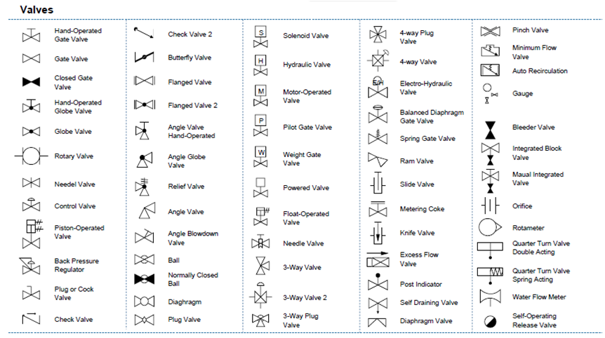
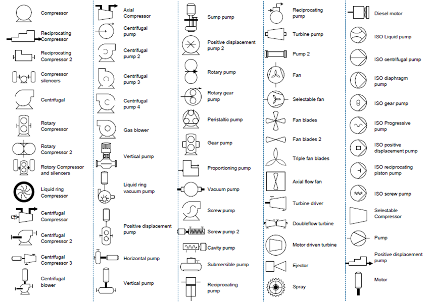
•In both diagrams arrows show the flow of material and symbols show tanks, valves, and other equipment. The symbols used vary somewhat from organization to organization. So you may see several different symbols that all represent a motor.
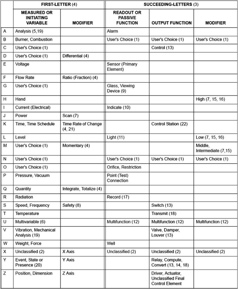
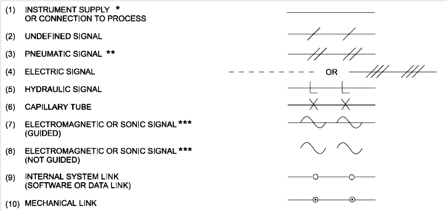
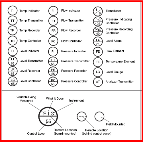
P&ID symbols is provided below: