The most common type of I/O interface module is the discrete type. This type of interface connects field input devices of the ON/OFF nature such as selector switches, push buttons and limit switches.
Similarly output control is limited to devices such as lights, small motors, solenoids and motor starters that require simple ON/OFF switching.
Each discrete I/O module is powered by some field supplied voltage source. Since these voltages can be of different magnitude or type, I/O modules are available at various ac and dc voltage rating as listed in Table 21.1.
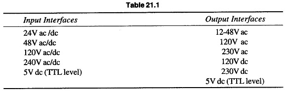
Figure. 21.70 shows a block diagram for one input of a typical ac interface input module.
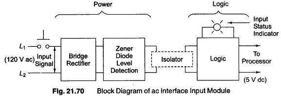

The input circuit is composed of two basic sections—the power section and the logic section. The power and logic sections are normally coupled together in a circuit, which electrically separates the two.
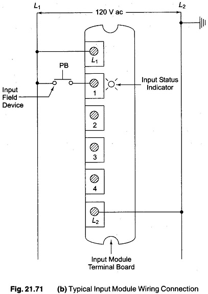
A simplified schematic and wiring diagram for one input of a typical ac input module is shown in Fig. 21.71(a) and (b). When the push button is closed, 120V ac is applied to the bridge rectifier through’ R1 and R2.
This produces a low level dc voltage which is applied across the LED of the optical isolator. The Zener diode (ZD ) voltage rating sets the minimum level of voltage that can be detected . When the light from the LED strikes the photo transistor, it switches into conduction and the status of the push button is communicated in logic or low level dc voltage to the processor.
The optical isolator not only separates the higher ac input voltage from the logic circuits, but also prevents damage to the processor due to line voltage transients.
Optical isolation also helps reduce the effects of electrical noise, common in industrial environment which can cause erratic operation of the processor. Coupling and isolation can be accomplished by use of a pulse transformer.
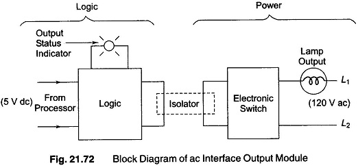
Figure. 21.72 shows a diagram for one output of a typical interface output module. Similar to the input module, it is composed of two basic sections, the power section and the logic section, coupled by an isolation circuit. The output interface can be considered of as a simple electronic switch to which power is applied to control output device.
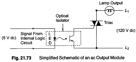
A simplified schematic and wiring diagram for one output of a typical ac output module is shown in Fig. 21.73. As part of its normal operation, the processor sets the output states according to the logic program.
When the processor calls for an output, a voltage is applied across the LED of the isolator. The LED then emits light which switches on the phototransistor into conduction. This, in turn, switches a semiconductor switch such as Triac into conduction which turns on the lamp. Since the triac conducts in either direction, the output to lamp is ac.
The triac rather than having ON and OFF status, actually has low and high resistance levels respectively. In its OFF state (high resistance) a small leakage current of a few mA still flows through the triac.
As with input circuits, the output interface is usually provided with LED’s that indicate the status of each output. In addition, if the module contains a fuse, a fuse status indicator may also be used as shown in Fig. 21.74.

Individual ac outputs are usually limited by the size of the triac to 2 or 3A. The maximum current load for any one module is also specified. To protect the output module circuits, specified current ratings should not be exceeded.
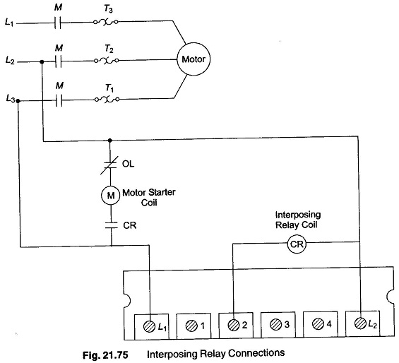
For controlling large loads, such as large motors, a standard control relay is connected to the output module. The contacts of the relay can then be used to control a large load or motor starter as shown in Fig. 21.75. When a control relay is used in this manner it is called an interposing relay.