In smaller PLCs the inputs are normally built in and are specified when purchasing the PLC.
For larger PLCs the inputs are purchased as modules, or cards, with 8 or 16 inputs of the same type on each card. For discussion purposes we will discuss all inputs as if they have been purchased as cards.
PLC Input Voltages
The list below shows typical ranges for input voltages, and is roughly in order of popularity.
- 12-24 Vdc
- 100-120 Vac
- 10-60 Vdc
- 12-24 Vac/dc
- 5 Vdc (TTL)
- 200-240 Vac
- 48 Vdc
- 24 Vac

PLC Input Cards
PLC input cards rarely supply power, this means that an external power supply is needed to supply power for the inputs and sensors.
The example in below Figure shows how to connect an AC input card.
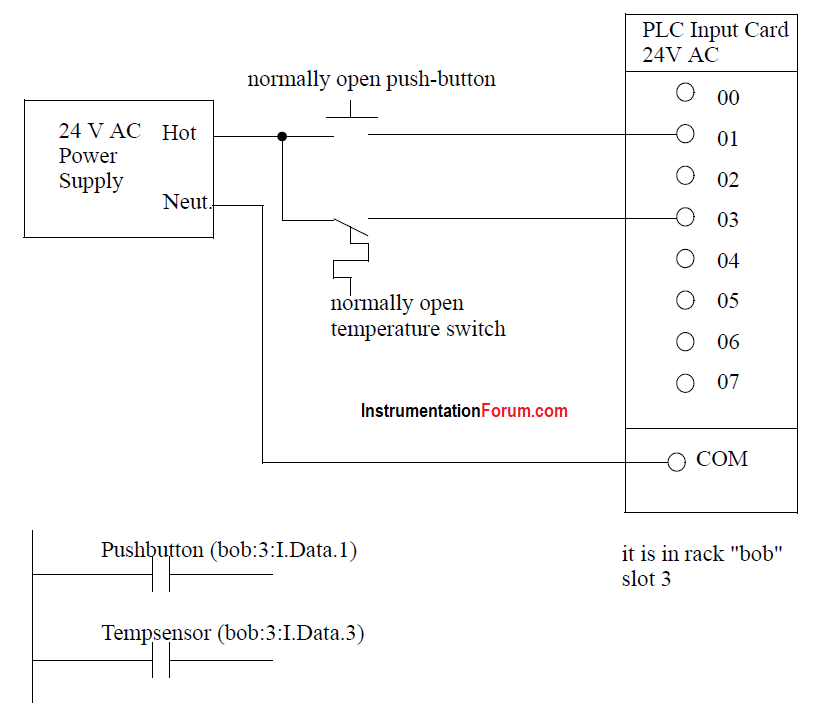
Figure: An AC Input Card and Ladder Logic
Note: inputs are normally high impedance. This means that they will use very little current.
In the example there are two inputs, one is a normally open push button, and the second is a temperature switch, or thermal relay.
Both of the switches are powered by the positive/ hot output of the 24Vac power supply - this is like the positive terminal on a DC supply.
Power is supplied to the left side of both of the switches. When the switches are open there is no voltage passed to the input card. If either of the switches are closed power will be supplied to the input card.
In this case inputs 1 and 3 are used - notice that the inputs start at 0. The input card compares these voltages to the common. If the input voltage is within a given tolerance range the inputs will switch on.
Ladder logic is shown in the figure for the inputs. Here it uses Allen Bradley notation for ControlLogix. At the top is the tag (variable name) for the rack.
The input card (’I’) is in slot 3, so the address for the card is bob:3.I.Data.x, where ’x’ is the input bit number. These addresses can also be given alias tags to make the ladder logic less confusing.
NOTE: The design process will be much easier if the inputs and outputs are planned first, and the tags are entered before the ladder logic. Then the program is entered using the much simpler tag names.
Many beginners become confused about where connections are needed in the circuit above. The key word to remember is circuit, which means that there is a full loop that the voltage must be able to follow.
In above Figure we can start following the circuit (loop) at the power supply. The path goes through the switches, through the input card, and back to the power supply where it flows back through to the start. In a full PLC implementation there will be many circuits that must each be complete.
A second important concept is the common. Here the neutral on the power supply is the common, or reference voltage. In effect we have chosen this to be our 0V reference, and all other voltages are measured relative to it. If we had a second power supply, we would also need to connect the neutral so that both neutrals would be connected to the same common.
Often common and ground will be confused. The common is a reference, or datum voltage that is used for 0V, but the ground is used to prevent shocks and damage to equipment. The ground is connected under a building to a metal pipe or grid in the ground.
This is connected to the electrical system of a building, to the power outlets, where the metal cases of electrical equipment are connected. When power flows through the ground it is bad. Unfortunately many engineers, and manufacturers mix up ground and common. It is very common to find a power supply with the ground and common mislabeled.
Remember - Don’t mix up the ground and common. Don’t connect them together if the common of your device is connected to a common on another device.
One final concept that tends to trap beginners is that each input card is isolated. This means that if you have connected a common to only one card, then the other cards are not connected. When this happens the other cards will not work properly. You must connect a common for each of the output cards.
PLC Card Types
There are many trade-offs when deciding which type of input cards to use.
-
DC voltages are usually lower, and therefore safer (i.e., 12-24V).
-
DC inputs are very fast, AC inputs require a longer on-time. For example, a 60Hz wave may require up to 1/60sec for reasonable recognition.
-
DC voltages can be connected to larger variety of electrical systems.
-
AC signals are more immune to noise than DC, so they are suited to long distances, and noisy (magnetic) environments.
-
AC power is easier and less expensive to supply to equipment.
-
AC signals are very common in many existing automation devices.
PLC Input Circuits
PLC inputs must convert a variety of logic levels to the 5Vdc logic levels used on the data bus.
This can be done with circuits similar to those shown below.
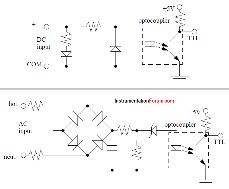
Basically the circuits condition the input to drive an optocoupler. This electrically isolates the external electrical circuitry from the internal circuitry.
Other circuit components are used to guard against excess or reversed voltage polarity.