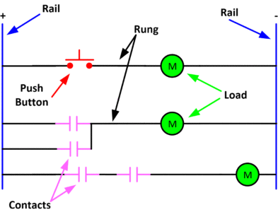
The ladder diagram, shown in figure, is easy to read since there are only two basic parts- the rails and the rungs.
The rails are the two dark vertical lines that represent the power source to the control circuit.
The control circuit voltage is usually rated at 12V-120V depending on the rated values of the loads connected in the circuit.
The rungs are the horizontal lines that illustrate how the control devices and loads are interconnected to make up the control circuit.

1.A ladder diagram translates similarly to a book. Read the ladder diagram from left to right then up to down in order to understand the sequence of the operation.
-
The loads in a ladder diagram are always and shall be connected in parallel on the rungs.
-
The load is the last component connected to the right side of the rail unless there is a protective contact that opens the circuit in the case of an overload event.
-
Control devices are connected between the left side of the rail and the load or other control devices and the load. Control devices are never to be connected from the left rail to the right rail. The result of this type of connection will result in a short circuit.