PLC Ladder Logic for Auto Lock up system in the Supermarket
Control Purpose:
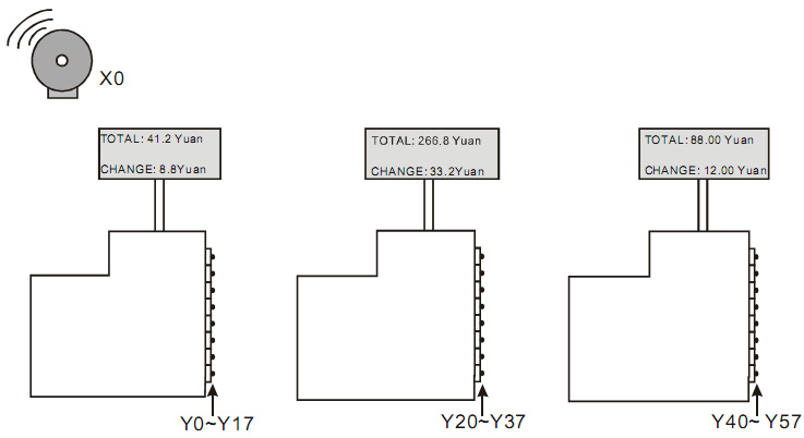
Once fire or robbery happened in the supermarket, locking up all cash drawers until the alarm situation is cleared.
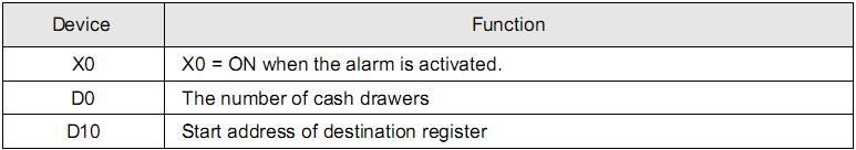
Devices:
Program Description:
-
The execution times of FOR~NEXT loop which decide the number of controlled cash counters can be controlled by the value in D0. Each cash counter has 16 drawers. In this program, D0 = K3, which means it can control 48 cash drawers in 3 counters.
-
F10 = K0, D10F1 represents D10; F10 = K1, D10F1 represents D11; F0 = K2, D10F1 represents D12; F0=K3, D10F1 represents D13.
-
When the alarm rings, X0 = ON. FOR ~ NEXT loop will be executed for 3 times and HFFFF will be sent to D10 ~ D12 in order. After the execution, the value in D10 ~ D12 will be sent to the external outputs. All the outputs Y will be set to be ON in this case. The system will lock up all the cash drawers.
-
When the alarm situation is cleared, X0 = OFF. FOR ~ NEXT loop will be executed for 3 times and H0 will be sent to D10 ~ D12 in order. After the execution, the value in D10 ~ D12 will be sent to the external outputs. All the outputs Y will be reset to be OFF in this case. The system will unlock all the cash drawers.
-
In this program, the index register F1 is used for storing single value in a data stack (series D registers). According to different application situations, users can make use of the data stack for controlling timers or counters.