Charge and discharge of a reservoir is a common process in industry as well as a need for mixing two or more substances. By using automated valves this process can be completely automated.
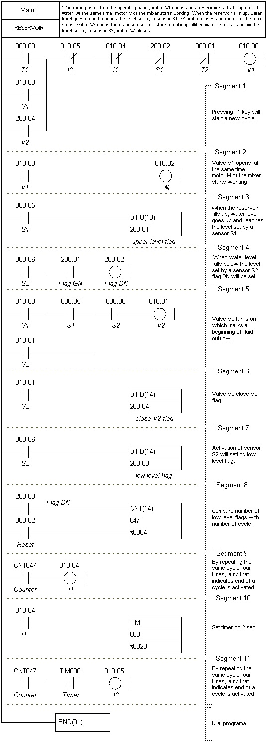
Let’s say that fluid used in the example is water, and that a reservoir has to be filled up and emptied four times. When you push T1 on the operating panel, valve V1 opens and a reservoir starts filling up with water. At the same time, motor M of the mixer starts working.
When the reservoir fills up, water level goes up and reaches the level set by a sensor S1. V1 valve closes and motor of the mixer stops. Valve V2 opens then, and a reservoir starts emptying. When water level falls below the level set by a sensor S2, valve V2 closes. By repeating the same cycle four times, lamp that indicates end of a cycle is activated. Pressing T1 key will start a new cycle.
Both types of differentiators are used in this example. You can get an idea of what their role is from picture below. Level S1 and S2 sensors provide information on whether fluid level goes beyond a specified value. This type of information is not important when you wish to know whether fluid level goes up or down in a certain sequence.
Mainly, event of approaching the upper level, or a moment when fluid that fills up a reservoir goes beyond upper level and activates sensor S1 is detected in segment 3 of a ladder diagram. Brief activation of IR200.02 output has as a consequence a turn off of an output V1 (valve for water, prevents further flow of water but also motor operation in the mixer). Moment prior to this (segment 5) valve V2 turns on which marks a beginning of fluid outflow. Other two differentiators (in segments 6 and 7) have a task of registering events such as closing a valve MV2 and drop in fluid level below allowed minimum.
Ladder diagram: