As with PLC input modules, output modules rarely supply any power, but instead act as switches.
External power supplies are connected to the output card and the card will switch the power on or off for each output.
PLC Output Voltages
Typical output voltages are listed below, and roughly ordered by popularity.
- 120 Vac
- 24 Vdc
- 12-48 Vac
- 12-48 Vdc
- 5Vdc (TTL)
- 230 Vac
Warning - Always Check Rated Voltages and Currents for PLC’s And Never Exceed!
PLC Output Cards
These cards typically have 8 to 16 outputs of the same type and can be purchased with different current ratings.
A common choice when purchasing output cards is relays, transistors or triacs.
Relays are the most flexible output devices. They are capable of switching both AC and DC outputs. But, they are slower (about 10ms switching is typical), they are bulkier, they cost more, and they will wear out after millions of cycles.
Relay outputs are often called dry contacts. Transistors are limited to DC outputs, and Triacs are limited to AC outputs. Transistor and triac outputs are called switched outputs.
Dry contacts
A separate relay is dedicated to each output. This allows mixed voltages (AC or DC and voltage levels up to the maximum), as well as isolated outputs to protect other outputs and the PLC.
Response times are often greater than 10ms. This method is the least sensitive to voltage variations and spikes.
Switched outputs
A voltage is supplied to the PLC card, and the card switches it to different outputs using solid state circuitry (transistors, triacs, etc.) Triacs are well suited to AC devices requiring less than 1A.
Transistor outputs use NPN or PNP transistors up to 1A typically. Their response time is well under 1ms.
PLC Output Circuits
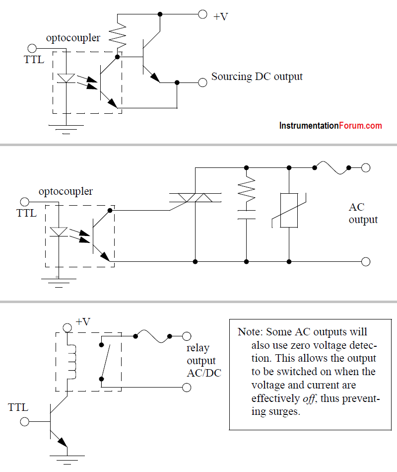
PLC outputs must convert the 5Vdc logic levels on the PLC data bus to external voltage levels. This can be done with circuits similar to those shown below.
Basically the circuits use an optocoupler to switch external circuitry. This electrically isolates the external electrical circuitry from the internal circuitry.
Other circuit components are used to guard against excess or reversed voltage polarity.
Caution is required when building a system with both AC and DC outputs.
If AC is accidentally connected to a DC transistor output it will only be on for the positive half of the cycle, and appear to be working with a diminished voltage.
If DC is connected to an AC triac output it will turn on and appear to work, but you will not be able to turn it off without turning off the entire PLC.
A transistor is a semiconductor based device that can act as an adjustable valve. When switched off it will block current flow in both directions. While switched on it will allow current flow in one direction only. There is normally a loss of a couple of volts across the transistor.
A triac is like two SCRs (or imagine transistors) connected together so that current can flow in both directions, which is good for AC current. One major difference for a triac is that if it has been switched on so that current flows, and then switched off, it will not turn off until the current stops flowing. This is fine with AC current because the current stops and reverses every 1/2 cycle, but this does not happen with DC current, and so the triac will remain on.
PLC Output Modules
A major issue with outputs is mixed power sources. It is good practice to isolate all power supplies and keep their commons separate, but this is not always feasible.
Some output modules, such as relays, allow each output to have its own common.
Other output cards require that multiple, or all, outputs on each card share the same common. Each output card will be isolated from the rest, so each common will have to be connected.
It is common for beginners to only connect the common to one card, and forget the other cards - then only one card seems to work!
PLC Output Card with Sinking
The output card shown in below Figure is an example of a 24Vdc output card that has a shared common. This type of output card would typically use transistors for the outputs.
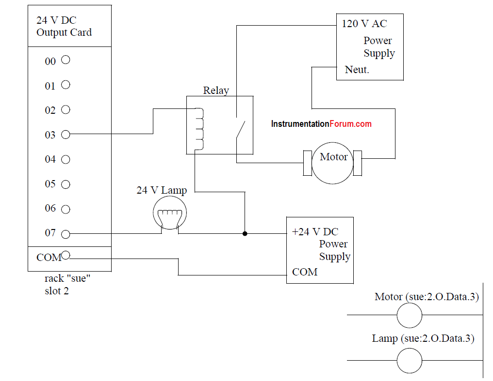
Figure: An Example of a 24Vdc Output Card (Sinking)
In this example the outputs are connected to a low current light bulb (lamp) and a relay coil. Consider the circuit through the lamp, starting at the 24Vdc supply.
When the output 07 is on, current can flow in 07 to the COM, thus completing the circuit, and allowing the light to turn on. If the output is off the current cannot flow, and the light will not turn on.
The output 03 for the relay is connected in a similar way. When the output 03 is on, current will flow through the relay coil to close the contacts and supply 120Vac to the motor.
Ladder logic for the outputs is shown in the bottom right of the figure. The notation is for an Allen Bradley ControlLogix.
The output card (’O’) is in a rack labelled ’sue’ in slot 2. As indicated for the input card, it is good practice to define and use an alias tag for an output (e.g. Motor) instead of using the full description (e.g. sue:2.O.Data.3).
This card could have many different voltages applied from different sources, but all the power supplies would need a single shared common.
PLC Output Card with Sourcing
The circuits in below Figure had the sequence of power supply, then device, then PLC card, then power supply. This requires that the output card have a common.
Some output schemes reverse the device and PLC card, thereby replacing the common with a voltage input.
The example in above Figure is repeated in below Figure for a voltage supply card.
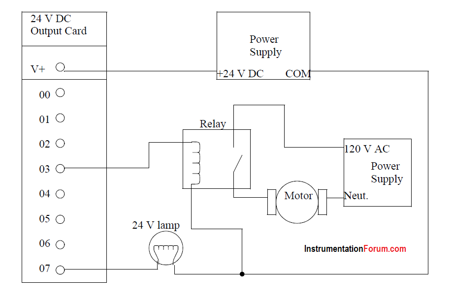
Figure: An Example of a 24Vdc Output Card With a Voltage Input (Sourcing)
In this example the positive terminal of the 24Vdc supply is connected to the output card directly. When an output is on power will be supplied to that output.
For example, if output 07 is on then the supply voltage will be output to the lamp. Current will flow through the lamp and back to the common on the power supply. The operation is very similar for the relay switching the motor.
Notice that the ladder logic (shown in the bottom right of the figure) is identical to that in Figure 3.5. With this type of output card only one power supply can be used.
PLC Relay Output
We can also use relay outputs to switch the outputs. The example shown in above Figures is repeated yet again in below Figure for relay output.
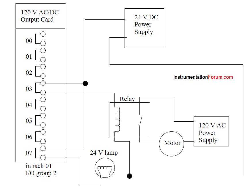
In this example the 24Vdc supply is connected directly to both relays (note that this requires 2 connections now, whereas the previous example only required one.) When an output is activated the output switches on and power is delivered to the output devices.
This layout is more similar to above Figure (sourcing) with the outputs supplying voltage, but the relays could also be used to connect outputs to grounds, as in above Figure (sinking).
When using relay outputs it is possible to have each output isolated from the next. A relay output card could have AC and DC outputs beside each other.