The PLC Process Simulator (automation)
“PSPLC” - is designed to work with PLCSIM v 5.x the part of Step7 and TIA Portal the Siemens™ PLC programing environment.
This universal process simulator is used for building various technological models.
Click below link
Download: PSPLC the PLC process simulator (DEMO) V1.2
Version 1.2 updated in Sep 2018
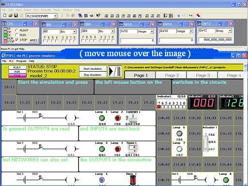
How does the simulator work?
- Similarly to the PLCSIM™ - the process simulator also works in cycles.
At the start of each cycle PS PLC reads both the decimal and analog OUTPUTS then the calculations for every devices are done.
The devices are worked out with the following order: circuits, buttons and switches, components such as: motors, actuators, valves and finally lights, indicators.
At the end of each cycle the process simulator sends all the INPUTS back to the PLC unit. The “PS PLC” works with the ratio of about 10 cycles per second.
Program versions:
-The DEMO version of the “PS PLC” allows to assign (connect) only up to 8 decimal INPUTS and OUTPUTS and 2 analog INPUTS and OUTPUTS.
The free DEMO version is sufficient for a tiny compact PLC.
-STANDARD: After activating the preceding limits are removed. There can be assigned up to both 80 decimal OUTPUTS and INPUTS and up to 5 analog OUTPUTS and INPUTS.
The STANDARD version of “PS PLC” is suitable for S300™.
(In preparation version PREMIUM that allows to assign many more INPUTS and OUTPUTS and to place more devices. Designed for the most sophisticated technological simulations based on S400™).
The first steps and connection:
Connection:
While the simulator starts it seeks for the connection automatically.
If the connection hasn’'t been established (STATUS ERROR) open the “Connection options” from the “Program Menu”, set the port number (usually 0 or 1) and select “Connect!”
There is a possibility to run a few independent “PSPLC’'s” each one connected to a different PLCSIM™ through the own port number.
“PSPLC” is connected properly despite the selected PG/PC interface.
(Whether it’'s: MPI, PROFIBUS, TCP/IP, ISO or LOCAL)
IMPORTANT !
DO NOT UPLOAD THE HARDWARE CONFIGURATION INTO THE PLCSIM™
Upload only the software into it.
Establishing the connection correctly between PLCSIM and the process simulator while working under TIA Portal.
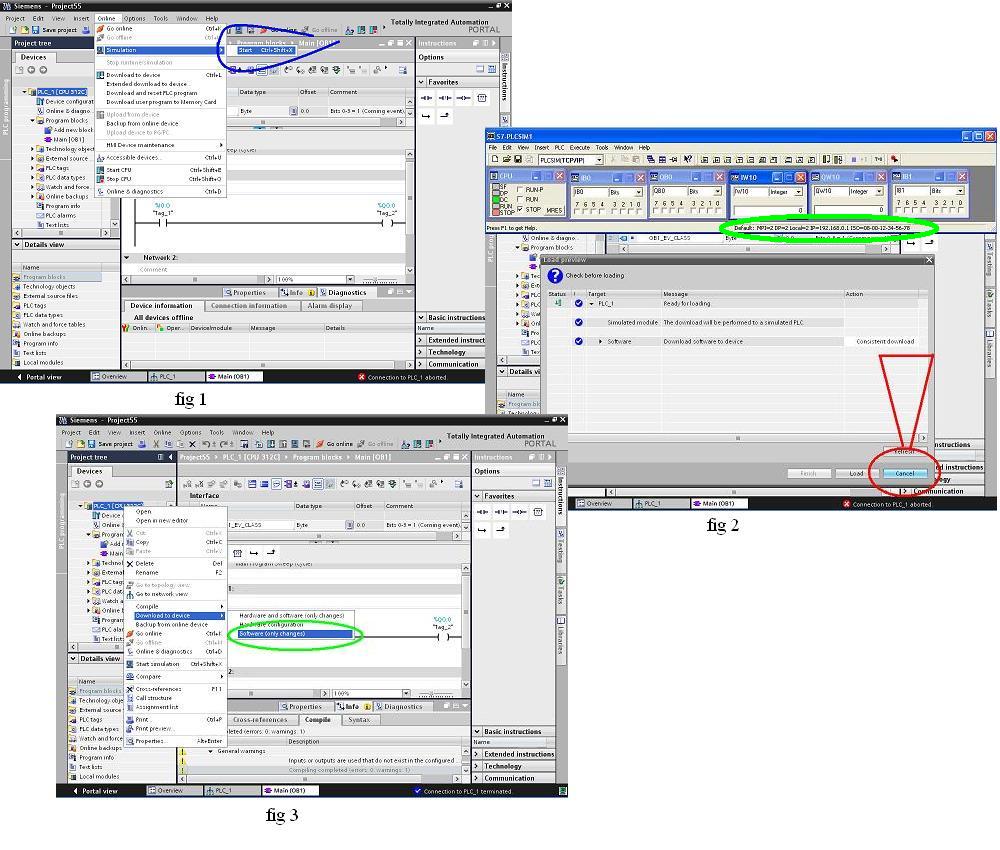
Select “Cancel” during starting the simulating (fig2), and then download to the PLC the program (fig3)
Program Menu:
“FILE MENU”: choose between: a “New”, “Open”, “Save”, “Save as:” the project or “Exit” the program.
“PLC MENU”: “Connect”, “Connection options:” as above
“RUN-P”, “RUN”, “STOP”: once again the same commands as on the main screen. After selecting the actual status is shown on the screen and the selected button changes its colour.
“PROGRAM / SIMULATOR OPTIONS”: choose the language version (as best after changing restart the program) and the units system (metric or British Imperial),
set the screen refresh and analog signals transmition ratio turn on or off the sound effects.
Record Graphs (up to 60 minutes) and select the folder for saving them (unlimited simulation time).
“HELP”: this “HELP” topic, “About” and “Activation” - read the first part of code and enter the second part.
TOOLBARS:
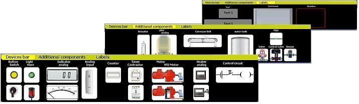
Press the left mouse button on one of the following: “Device bar”, “Additional components” or “Labels” to select the actual toolbar.
Press the left mouse button on the selected item to choose them, then press the left mouse button again on the WORKSPACE to put the object, right mouse button to cancel.
The decimal “OUTPUTS” and “INPUTS”:
There are both 10 decimal output modules and input modules consist of 8 lines each.
To avoid confusion all “OUTPUTS” on the devices’’ properties are the same as “OUTPUTS” on the PLC and similarly the “INPUTS”.
The “OUTPUTS” are used for controlling the devices placed and the "INPUTS for sending the signals back to the PLC.
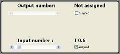
Click on the “assigned” checkbox to enable the scrollbar and set the output or input number.
Setting the “INPUTS” especially needs considering due to a possiblity of occuring two different signal states set by the two different devices at one “INPUT” at the same time.
The analog “OUTPUTS” and “INPUTS”:
There are both 5 analog output modules and input modules. Each analog value needs two bytes to be stored.
The value “27648” is a numerical equivalent of either: 100%, 20mA, or 10V.
The analog values can be both signed and unsigned.
Changing the colour of the INPUT or OUTPUT number
Normally open
Normally closed
Normally closed
Normally open
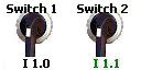
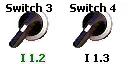
Buttons, switches and analog inputs
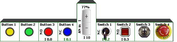
Press the right mouse button during the edition to enter the objects’’ properties. Buttons and switches can be normally open or normally closed.
Analog inputs can be signed or unsigned.
Press the left mouse button on the object during the simulation to change its state or value.
LEDs, Horns, Indicators.

LEDs should be turned on and off only by the OUTPUTs but in the simulation they can be also used for indicating the signal state at the INPUTs.
Timers, Contractors, Counters.
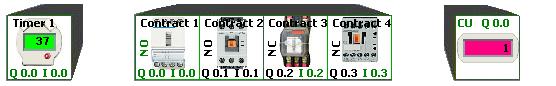
Timers and Contractors are normally open or closed.
Counters can be used to count impulses for a PLC programmer (not the program)
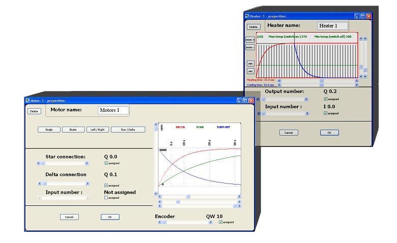
Actuators, Motors, Heaters.
Siloses, conveyors.
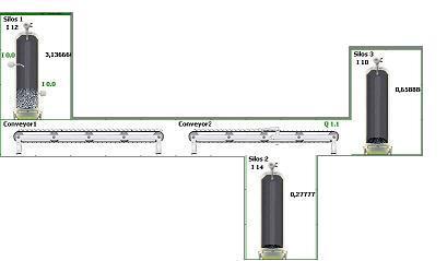
Select a SILOS from the toolbar and put it on the WORKSPACE, then press the right mouse button on the SILOS to enter its properties set the SILOS capacity, the colour of material and set up sensors.
In order to place a conveyor select it from the TOOLBAR hold the left mouse button and drag a conveyor towards left or right on the WORKSPACE
Press the right mouse button at the beginning of the conveyor to select the colour and amount of material conveyed, choose between silos or conveyor to specify the source of material taken
Press the right mouse button in the middle to add a DROPPER
Press the right mouse button at the end of the conveyor to set the OUTPUT for driven roller. Unless the material is taken by another conveyor (“Conveyor transports to” - leave disabled) select the destination SILOS
Tanks, pipes, valves, flow sensors.
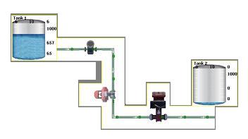
Select a TANK from the toolbar and put it on the WORKSPACE, press the right mouse button on the TANK to enter its properties adjust the TANK capacity and set up a level sensor.
To lay a pipe select it from the TOOLBAR hold the left mouse button and drag a pipe in any direction on the WORKSPACE.
The shape of the pipe doesn’‘t matter for the liquid flow. Only the settings in the pipe’'s properties are important.
To install a valve select it from the TOOLBAR and put the valve on the straight piece of pipe. (Apart from pipe elbows)
Make sure there is an unoccupied field above or on the left. Flow sensors can be fitted on any straight part of the pipe.
So far only single pipes can be laid (without Y connections). In some cases an additional TANK can be used as the Y connection
Control circuits.
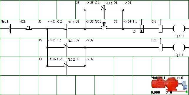
Control circuits - can be used for building simple control circuits such as junction boxes, control boxes.
A new CIRCUIT can be built by selecting it from the TOOLBAR then holding the left mouse button and dragging the CIRCUIT towards the right on the WORKSPACE.
First of all, the devices on the circuits (BUTTONS, SWITCHES, CONTRACTONS, RELAYS, CONTACTS) are different from the devices on the TOOLBAR
The beginning of each NETWORK can always be powered as if from a battery or fed by a PLC OUTPUT.
Control CIRCUITS are calculated before all other devices in each cycle. (see: “How does it work” at the top of the page)
Only the circuits set the decimal OUTPUTS so that they can be used for turning on and off all other devices or setting the decimal INPUTS ( the example circuit: star-delta motor starter )
(NOTICE. Circuits are not exactly calculated as the single wires.
It is presumed that each part of circuit conducts the electric current if there is a connection with both the begining and the end of the network)
For more complex circuits coils in particularly between the junction points may not work properly )
Graphs.
Graphs can be recorded for 1 hour. In order to obtain Graphs for longer last simulations the field “Save Graphs” in “Program Options” should be selected.
Graphs are saved every: 1,2,4,8,16 minutes - depending on the setting the scrollbar of the scale on the Graphs screen.
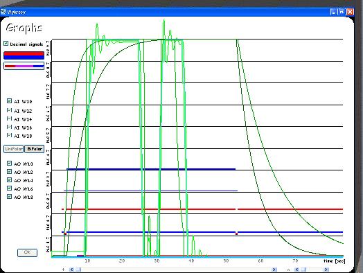
While the Graph is being saved the PSPLC and PLCSIM is being paused
Labels
In order to put the TEXT choose it from the TOOLBAR and put on the WORKSPACE.
Border can be placed by dragging it holding the left mouse button.
SCREEN allows to display the different texts.