Timer is an instruction that waits a set amount of time before doing something. The different kinds of timers are available with different manufacturers. Most of the timers are:
ON-delay Timer: This type of timer simply “delays turning on”. In other words after our sensor (input) turns on, the timer waits for some seconds say x secs before activating a solenoid valve (output). This is the most common timers. It is often called TON (timer on-delay), TIM (Timer) or TMR (Timer).
OFF-delay Timer: This type of timer is the opposite of the on-delay This timer simply “delays turning OFF”. After our sensor (input) sees a target, the solenoid (output) is turned on. When the sensor no longer sees the target, the solenoid is held for some seconds, say x secs before turning it OFF. It is called a TOF (timer OFF-delay) and is less common than the on-delay type listed above.
Retentive or Accumulating Timer: This type of timers needs 2 inputs. One input starts the timing event (i.e. the clock starts ticking) and the other resets it. The ON/OFF delay timers above would be reset if the input sensor was not ON/OFF for the complete timers duration. This timers however holds or retains the current elapsed time when the sensor turns off in mid-stream. For example, if we wish to know how long a sensor is on during a 1 hr period. If we use one of the above timers they will keep resetting when the sensor turns OFF/ON. This timers however, will give us a total or accumulated time. It is often called an RTO (Retentive timers) or TMRA (accumulating timer).
To use a timer, we typically need to know two things.
- What will enable the timer? There is typically one of the input (sensor).
- How long we want to delay before we react. For example, let us say, 5 sec, before a solenoid is turned on.
When instructions before the timers symbol are true, the timers starts “ticking” when the time elapses the timer will automatically close its contacts. When the program is running on the PLC, the program typically displays the elapsed or `accumulated’ time, so that the current value can be seen. Typically timers can tick from 0 to 9999 or 0-65535 times. Most of the PLC used have 16 bit timers. Hence, a 0-9999 is for a 16 bit BCD and 0-65535 for a 16 bit binary. Each tick of the clock is equal to x seconds.
Typically each manufacturer offers several different ticks. Most manufacturers offer 10 ms and 100 ms increment or tick of the clock. Several manufacturers also offer 1 ms as well as 1 second increments. These different increment timers work the same as above but sometimes have different names to show their timebase. Some of them are TMH (high speed timer), TMS (super high speed timer) and TMRAF (accumulating fast timer).
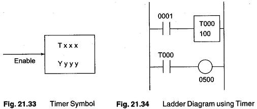
A typical timers instruction symbol is shown in Fig. 21.33. This timers is the on-delay type and is named Txxx. When the enable input is on the timers starts. When it ticks up-to yyyy (the preset value) times, it will turn on its contacts. The duration of a tick (increment) varies with vendor or user and the time base used (for a tick may be of lms or 1 sec or …).
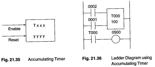
In the ladder diagram shown in Fig. 21.34 , when the input 0001 is turned on. The timer T000 (a 100 ms increment timer) starts ticking. It will tick 100 times. Each increment is of 100ms, hence the timers will be a 100 tick x 100 ms = 10000 ms (i.e. 10 second) timer. When 10 secs have elapsed the T000 contacts closes and the output 0500 is turned on. When the input 0001 turns off, the timer T000 will reset back to 0 causing its contacts to turn off thereby output 0500 is turned back off.
An accumulating timers, is as shown in Fig. 21.35. Let this timers be named Txxx. When the enable input is ON the timer starts to tick. When it ticks yyyy (the preset value) times, it will turn on its contacts that is used later in the program. The duration of a tick (increment) varies with the user and the timebase used. (A tick can be a 1 ms or 1 sec or …) If however the enable input turns off before the timers has completed, the current value will be retained. When the input turns back on, the timer will continue from where it left off. The only way to force the timers back to its preset value to start again is to turn on the reset input.
A ladder diagram is shown in Fig. 21.36 consisting of the symbol of the timer. When the input 0002 turns on, the Timer T000 (a 10 ms increment timers in this case) starts ticking. It will tick 100 times. Each tick or increment is 10 ms so the time will be a 100 x 10 ms = 1000 ms = 1 second timers. When 1 second is elapsed, the T000 contacts closes, output 0500 turns on. If input 0002 turns back OFF, the current elapsed time will be retained. When the 0002 turns back on, the timer will continue when it left off. When input 0001 turns on (true) the timers T000 will reset back to 0 causing its contacts to turn off (false) thereby making output 0500 turn back off.
When creating a timers that lasts a few seconds, or more, the precision or accuracy is of not much significance. But in the timers that have duration in ms range, precision and accuracy is very significant.
Basically there are two types of errors in general when using a timer. The first is called an input error and the other is called the output error. The total error is the sum of both the input error and output errors.
Input Errors: An input error occurs depending upon when the timers input turns on during the scan cycle. When the input turns on immediately after the PLC looks at the status of the inputs during the scan cycles, the input error will be at its largest (i.e. More than 1 full scan time). This is because as seen in the scan time, the inputs are looked at once during a scan. If it was not on when the PLC looked or scanned and turns on later in the scan, obviously an error would occur. Further, we have to wait until the timers instruction is executed during the program part of the scan. If the timer instructions is the last on the rung then the error could be quite large.
Output Error: An output error occurs depending upon, when in the ladder the timers actually ‘times out’ (ceases) and when the PLC finishes executing the program to get to the part of the scan when it updates the output. This is because the timers finishes during the program execution but the PLC must first finish executing the remainder of the program before it can turn on the appropriate output.
Figure 21.37 illustrates the worst possible input error.
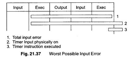
- Total input error
- Timers input physically on
- Timers instruction executed
As seen from the Fig. 21.37, the worst possible input error would be 1 complete scan time + 1 program execution time. (A program execution time varies from program to program.)
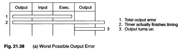
Figure 21.38 (a) illustrates the worst possible output error. Again the worst possible output error can be 1 complete scan time.
Based on the figure, we can see that the total worst possible timers error would be equal to : 1 scan time + 1 program execution time + 1 scan time = 2 scan times + 1 program execution time.
Even though most manufacturers currently have timers with 1 ms increments, they really should not be used for duration less than a few ms. This assumes that your scan time is 1 ms. For example if your scan time is 5 ms, then a timers with a duration less than about 15 ms should not be used.
In most applications these errors are insignificant, but in some high speed or precise applications, these errors can be very significant. These errors are software errors. There is also a hardware input error as well as hardware output error.
The hardware input error is caused by the time it takes for the PLC to actually realize that the input is ON when it scan its inputs. Typicilly this duration is about 10 ms. This is because many PLCs require that an input should be physically on for a few scans before it determines its physically on (to eliminate noise or bouncing inputs).
The output error is caused by the time it takes when the PLC tells its output to physically turn on until the moment it actually does. Typically a transistor takes about 0.5 ms whereas a mechanical relay takes about 10 ms.