Many control tasks require the programming of time. For example, cylinder 2 is to extend, if the cylinder 1 is retracted- but only after a delay of few seconds. The timers of a PLC are realized in the form of software modules and are based on the generation of digital timing. Memory space is allocated in system memory to store the values of the delay time. The representation of the timer address varies from manufacturer to manufacturer. For sake of understanding we shall as T1, T2 for timer addresses. The typical number of timers available in commercial PLC are 64, 128, 256 , 512 or even more. To explictiy reset timer, an RLO of 1 has to be applied at the reset port.
There are two types of PLC timer
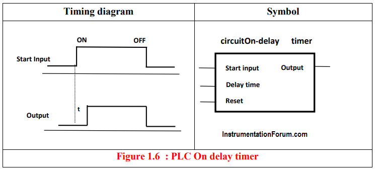
PLC on delay timer :
The timer will be ON state when it recieves a start input siganl and The signal state of output changes to 0 from 1 , when preset timing is reached. The signal state of the output changes from 0 to 1 when preset time has been reached with reference to change of RLO (Result of logic operation) from 0 to 1(ON) at the start input .Functional diagram is shown in below fig.
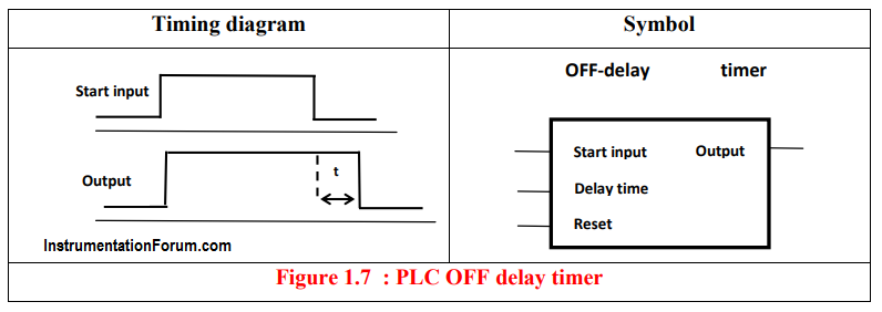
PLC off delay timer :
The timer will be ON state when it recieves a start input siganl and The signal state of output changes to 1from 0 , when preset timing is reached. The signal state of the output changes from 1 to 0 when preset time has been reached with reference to change of RLO from 1 to 0(OFF) at the start input. Functional diagram is shown in Figure 1.7