The PLC takes a certain amount of time to react to changes. The total response time of the PLC is a fact that has to be considered while selecting a PLC for some application where speed is a concern.
For example, if you take a moment off to look away from this text and see a picture on the wall. Your eyes actually see the picture before the brain responds to say “Oh there’s a picture on the wall”. In this example your eyes can be considered as the sensor. The eyes are connected to the input circuit of your brain. The input circuit of the brain takes a certain amount of time to realize that the eyes saw something, eventually when the brain realizes that the eyes have seen something and it processes the data. It then sends an output signal to your mouth which in turn receives this data and begins to response to it. Eventually your mouth comments on the picture.
In this example, we had to respond to three things:
Input: It took a certain amount of time for the brain to notice the input signal from the eyes.
Execution: It took a certain amount of time to process the information received from the eyes. Consider the program to be ‘If the eyes see a good picture then output appropriate worth to the mouth’.
Output: The mouth receives a signal from the brain and eventually gives the comment.
Hence, Input Response Time + Program Execution Time + Output Response Time = Total Response Time
Having understood the concept behind the response time, let us see what happens in a typical PLC Applications. The PLC can only see an input turn ON/OFF when its looking. In other words, it only looks at its inputs during the check input status part of the scan.
In the diagram shown in Fig. 21.24, input 1 is not seen until scan 2. This is because when input 1 is turned ON, scan 1 had already finished looking at the inputs. Similarly input 2 is not seen until scan 3. This is also because when the input 2 is turned ON, scan 2 had already finished looking at the inputs.
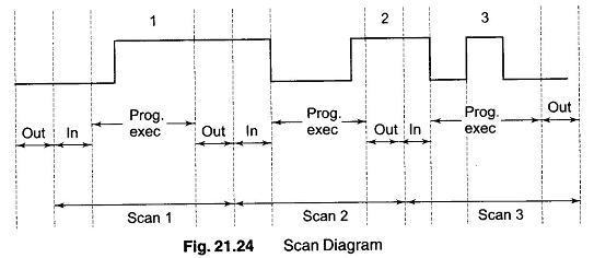
Input 3 is never seen, this is because when scan 3 was looking at the inputs, signal 3 was not ON yet. It turns OFF before scan 4 looks at the inputs. Therefore, signal 3 is never seen by the PLC.
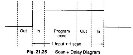
To avoid this, the input should be ON for at least 1 input delay + one scan time as shown in Fig. 21.25.
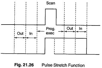
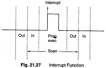
If the input was not long enough, then the PLC does not see the input turn ON, which is not desirable, hence, there are two ways to overcome this disadvantage. One is using Pulse Stretch function shown in Fig. 21.26. This function extends the length of the input signal until the PLC looks at the input during the next scan, i.e. it stretches the duration of the pulse. The other method is the Interrupt function as shown in Fig. 21.27. This function interrupts the scan to process a special routine that has been written, that is, as soon as the input turns ON, regardless of where the scan currently is; the PLC Applications immediately stops what it is doing and executes an interrupt routine. After it has done executing the interrupt routine, it goes back to the point it stopped or was interrupted or left OFF at and continues on with the normal scan process.