Pneumatic actuators are commonly used to actuate control valves and are available in two main forms; piston actuators (Figure 1) and diaphragm actuators (Figure 2).
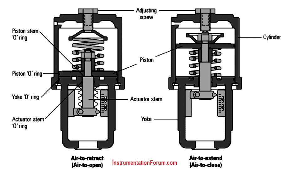
Figure 1. Typical piston actuators
Piston actuators are generally used where the stroke of a diaphragm actuator would be too short or the thrust too small. Compressed air is applied to a solid piston contained within a solid cylinder. Piston actuators can be single acting or double acting, can withstand higher input pressures, and can offer smaller cylinder volumes, which can act at high speed.
Diaphragm actuators apply compressed air to a flexible membrane called the diaphragm. Figure 19 shows a rolling diaphragm where the effective diaphragm area is virtually constant throughout the actuator stroke. These types of actuators are single acting, in that air is only supplied to one side of the diaphragm, and they can be either direct acting (spring-to-retract) or reverse acting (spring-to-extend).
REVERSE ACTING (SPRING-TO-EXTEND)
The operating force is derived from compressed air pressure, which is applied to a flexible diaphragm. The actuator is designed so that the force resulting from the air pressure, multiplied by the area of the diaphragm, overcomes the force exerted (in the opposite direction) by the spring(s).
The diaphragm in figure 2 is pushed upwards, pulling the spindle up, and if the spindle is connected to a direct acting valve, the plug is opened. The actuator is designed so that with a specific change of air pressure, the spindle will move sufficiently to move the valve through its complete stroke from fully-closed to fully-open.
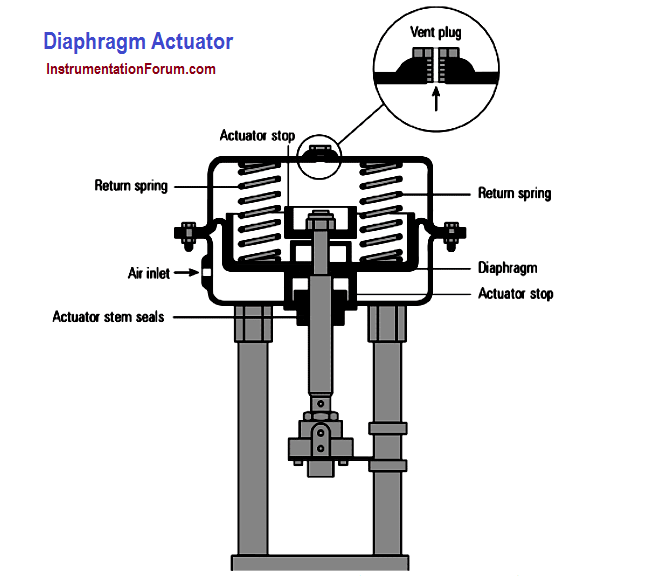
Figure 2. Diaphragm actuator
As the air pressure decreases, the spring(s) moves the spindle in the opposite direction. The range of air pressure is equal to the stated actuator spring rating, for example 0.2 - 1 bar. With a larger valve and/or a higher differential pressure to work against, more force is needed to obtain full valve movement.
To create more force, a larger diaphragm area or higher spring range is needed. This is why control manufacturers offer a range of pneumatic actuators to match a range of valves comprising increasing diaphragm areas, and a choice of spring ranges to create different forces.
The diagrams in figure 3 show the components of a basic pneumatic actuator and the direction of spindle movement with increasing air pressure.
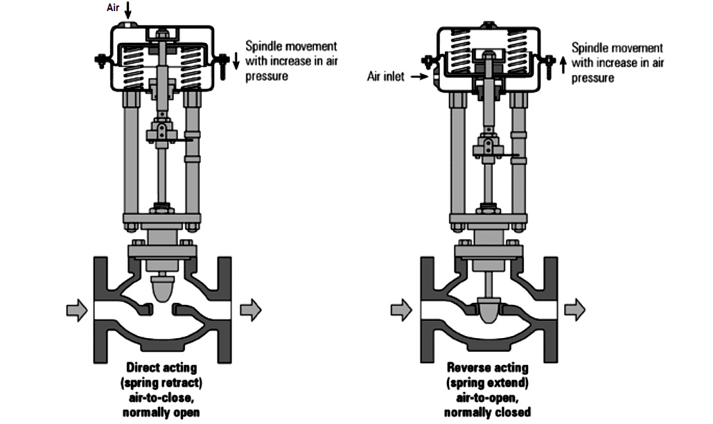
Figure 3. Valve and actuator configurations
DIRECT ACTING ACTUATOR (SPRING-TO-RETRACT)
The direct acting actuator is designed with the spring below the diaphragm, and air supplied to the space above the diaphragm. The result, with increasing air pressure, is spindle movement in the opposite direction to the reverse acting actuator. The effect of this movement on the valve opening depends on the design and type of valve used, and is illustrated in figure 3.
The alternative, which is shown in figure 4, A direct acting pneumatic actuator coupled to a control valve with a reverse acting plug. The choice between direct acting and reverse acting pneumatic controls depends on what position the valve should revert to in the event of failure of the compressed air supply.
Should the valve close or be wide-open? This choice depends upon the nature of the application and safety requirements. It makes sense for steam valves to close on air failure, and cooling valves to open on air failure. The combination of actuator and valve type must be considered.
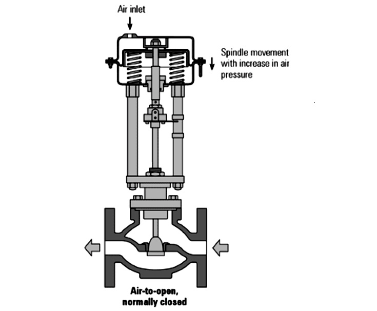
Figure 4. Direct acting actuator and reverse acting control valve
Reference - Source: Spiraxsarco
More info -