The Figure shows the construction of a rotary type potentiometer sensor employed to measure the linear displacement. The potentiometer can be of linear or angular type.
Potentiometer Sensor
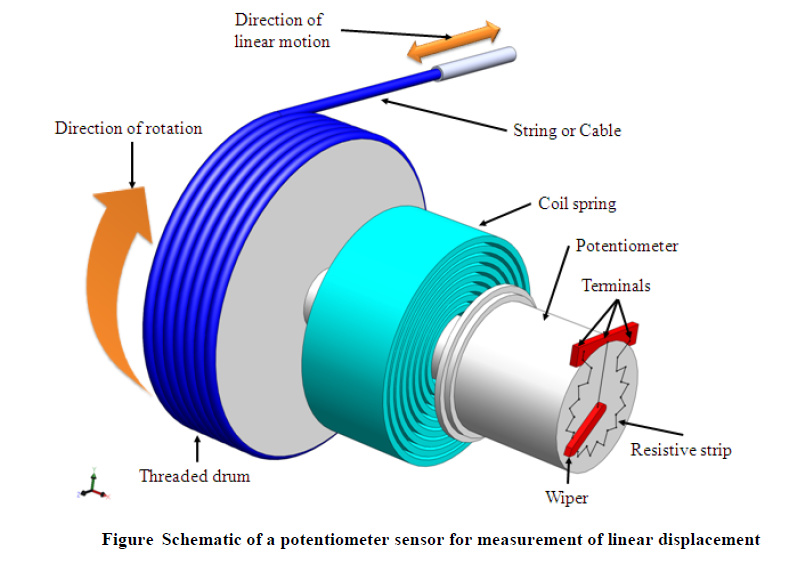
It works on the principle of conversion of mechanical displacement into an electrical signal. The sensor has a resistive element and a sliding contact (wiper). The slider moves along this conductive body, acting as a movable electric contact.
The object of whose displacement is to be measured is connected to the slider by using
• a rotating shaft (for angular displacement)
• a moving rod (for linear displacement)
• a cable that is kept stretched during operation
The resistive element is a wire wound track or conductive plastic. The track comprises of large number of closely packed turns of a resistive wire. Conductive plastic is made up of plastic resin embedded with the carbon powder. Wire wound track has a resolution of the order of ± 0.01 % while the conductive plastic may have the resolution of about 0.1 μm.
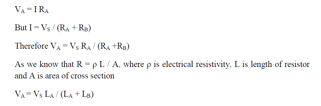
During the sensing operation, a voltage Vs is applied across the resistive element. A voltage divider circuit is formed when slider comes into contact with the wire. The output voltage (VA) is measured as shown in the below figure.
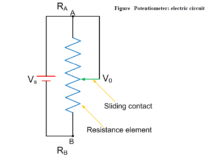
The output voltage is proportional to the displacement of the slider over the wire. Then the output parameter displacement is calibrated against the output voltage VA.
Applications of potentiometer
These sensors are primarily used in the control systems with a feedback loop to ensure that the moving member or component reaches its commanded position.
These are typically used on machine-tool controls, elevators, liquid-level assemblies, forklift trucks, automobile throttle controls. In manufacturing, these are used in control of injection molding machines, woodworking machinery, printing, spraying, robotics, etc. These are also used in computer-controlled monitoring of sports equipment.