Correcting power factor is a typical power control technique. Power factor correction is described in this article.
Power Factor Correction
Active power, measured in kilowatt (kW), is the real power (shaft power, true power) used by a load to perform a certain task. However, there are certain loads like motors, which require another form of power called reactive power (kvar) to establish the magnetic field. Although reactive power is virtual, it actually determines the load (demand) on an electrical system.
Electrical capacity required for some electrical equipment is referred to as “apparent power (kVA)”, that is, the vector sum of “active power” and “reactive power (lagging / leading)”. Most of the power machineries are driven by three-phase induction motors, which are inductive loads. When an inductive load is driven, the sine wave of the load current flows at the same frequency as the sine wave of the voltage, but lags the voltage wave cycle slightly.
When both current and voltage source waves cross zero and maximum value at the same time, the power factor is said to be unity, and the entire power can be utilised as real power.
The ‘Apparent Power-kVA’ is equal to ‘the real Power-kW”. When the current wave is slightly lagging the voltage wave, the power factor is said to be lagging and is less than unity.
The real power is less than the apparent power due to this lag. A lagging power factor is not beneficial to a power consumer as the billing is includes charges towards the kVA used, while the actual utilisation is less. It is also not beneficial for the power supplier whose system power factor is also affected.
Equipment used in most industries such as drives, controllers, etc., are inductive loads, which lower the power factor. The power factor is the ratio between active power (kW) and total power (kVA), or the cosine of the angle between active and total power. A high reactive power will increase this angle and as a result the power factor will be lower.
A vector diagram of power factor is shown in Figure
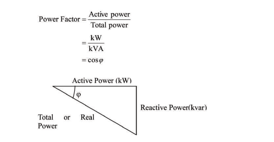
In a typical applications, since a large number of induction motors are used, the power factor will be low and needs to be improved or corrected.
The power factor can be improved by installing power factor correction capacitors to the plant’s power distribution system. They act as advancing reactive power generators and therefore reduce the amount of lagging reactive power, and thus the total power, generated by the utilities.
To improve or correct the power factor, apparent electrical capacity required for the electrical equipment should be decreased by canceling the lagging reactive power by the use of leading reactive power unit that can also reduce energy loss in cables, transformers, etc., before reaching to load equipment.
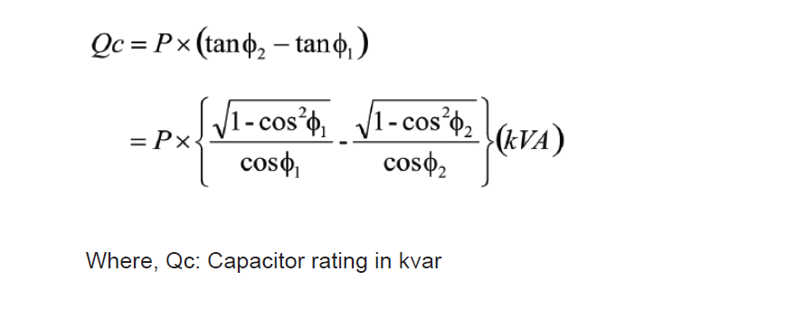
Rating of capacitor to be required for power factor correction can be calculated by the following vector equation.
Capacitor Panel
Capacitor panels consist of some equipment such as condensers for power factor correction, series reactors meters, relays, etc
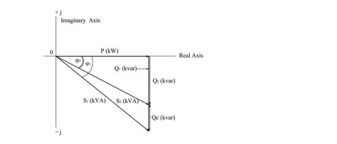
Where, S1 : Apparent power (kVA) = P – jQ1 (Before correction)
S2 : Apparent power (kVA) = P – jQ2 (After correction)
P : Active power (kW)
Q1 : Lagging reactive power (kvar) (Before correction)
Q2 : Lagging reactive power (kvar) (After correction)
Qc : Capacity of condenser (Advancing reactive power) (kVA)
cosφ1 : Power factor before correction
cosφ2 : Power factor after correction
Condenser (Capacitor)
Induction motors, which are inductive loads, generate lagged-phase reactive power. Phase-advanced condensers (capacitor) have the function of compensating the lagged-phase reactive power to improve power factor. The effects gained from the condensers vary according to the points to be installed.
For example, it is effective to install a condenser on the secondary side of a transformer if reduction in load and loss of the transformer is targeted. With regard to O&M, the capacitor’s reactive power acts during light load (when power equipment has stopped), and when the current leads the voltage in the circuit so that leading power factor occurs, and the terminal voltage of the load increases causing adverse effects on the equipment.
To prevent this phenomenon, the capacitor may need to be isolated, or an automatic power factor regulator may need to be installed. Normally, a capacitor unit comprises of individual capacitor elements arranged in parallel/ series connected groups within a steel enclosure.
An internal discharge device is a resistor that reduces the unit residual voltage to 50V or less in 5 minutes. Capacitor units are available in a variety of voltage ratings from 240 V – 66,000 V and sizes (2.5 kvar – about 1,000 kvar).
The capacitors can be with external fuses or internal fuses, or both. An internal fuse is a small fuse wire connected to each capacitor element, encapsulated in a wrapper. When a fault occurs in a particular element, the particular fuse melts, disconnecting the affected element only, and permitting the other elements to function without interruption.
An external fuse unit typically protects each capacitor unit in a bank. In an oil-impregnated capacitor, the internal pressure may increase resulting in expansion due to excessive current because of the failure of internal elements. This leads to leakage of oil from the capacitor unit and failure of the capacitor. Care should be taken to select capacitors with sufficient cooling volume.
When a capacitor circuit is switched on, there is an inrush current, which is likely to damage the capacitor. A choke or series reactor is used to control the inrush current.
Series Reactor
The major functions of a series reactor are to protect the capacitor by means of the following:
• Limiting inrush current during switching
• Limiting resonance and protection of capacitor banks
• Harmonic filtration
• Lower loss and noise level
Power Factor Correction at Motor Panel
Power factor can be increased by installing low voltage capacitor in parallel with the motor.
This enables the current to be reduced. Moreover, distortion waveform can also be stabilized by connecting a series reactor.