In standard P&IDs, the process flow lines, such as process fluid and steam, are indicated with heavier solid lines than the lines that are used to represent the instrument. The instrument signal lines use special markings to indicate whether the signal is pneumatic, electric, hydraulic, and so on. two types of instrument signals are used: double cross-hatched lines denote the pneumatic signals to the steam control valve and the process outlet flow control valve, and a dashed line is used for the electrical control lines between various instruments.
In process control applications, pneumatic signals are almost always 3 to 15 psig (i.e., pounds per square inch, gauge pressure), and the electric signals are normally 4 to 20 mA (milliamperes) DC (direct current).
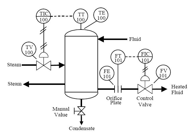
A balloon symbol with an enclosed letter and number code is used to represent the instrumentation associated with the process control loop. This letter and number combination is called an instrument identification or instrument tag number.
The first letter of the tag number is normally chosen so that it indicates the measured variable of the control loop. In the sampleP&ID shown, T is the first letter in the tag number that is used for the instruments in the temperature control loop. The succeeding letters are used to represent readout or passive function or an output function, or the letter can be used as a modifier.
For example, the balloon in Figure marked TE represents a temperature element and that marked TIC is a temperature-indicating controller. The line across the center of the TIC balloon symbol indicates that the controller is mounted on the front of a main control panel. No line indicates a field-mounted instrument, and two lines means that the instrument is mounted in a local or field-mounted panel. Dashed lines indicate that the instrument is mounted inside the panel.
Normally, sequences of three- or four-digit numbers are used to identify each loop. In our process example, we used loop numbers 100 and 101. Smaller processes use three-digit loop numbers; larger processes or complex manufacturing plants may require four or more digits to identify all the control loops.
Special marks or graphics are used to represent process equipment and instruments. For example, in our P&ID example in Figure two parallel lines represent the orifice plate that is used to detect the discharge flow from the process heater.