In electrical engineering, a protective relay is a complex electromechanical apparatus, often with more than one coil, designed to calculate operating conditions on an electrical circuit and trip circuit breakers when a fault is detected. Unlike switching type relays with fixed and usually ill-defined operating voltage thresholds and operating times, protective relays have well-established, selectable, time/current (or other operating parameter) curves.
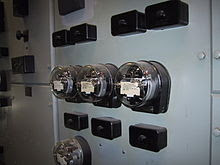
Such relays may be elaborate, using arrays of induction disks, shaded-pole magnets, operating and restraint coils, solenoid-type operators, telephone-relay contacts, and phase-shifting networks. Protection relays respond to such conditions as over-current, over-voltage, reverse power flow, over- and under- frequency. Distance relays trip for faults up to a certain distance away from a substation but not beyond that point. An important transmission line or generator unit will have cubicles dedicated to protection, with many individual electromechanical devices.
The various protective functions available on a given relay are denoted by standard ANSI Device Numbers. For example, a relay including function 51 would be a timed overcurrent protective relay. Design and theory of these protective devices is an important part of the education of an electrical engineer who specializes in power systems. Today these devices are nearly entirely replaced with microprocessor-based digital protective relays (numerical relays) that emulate their electromechanical ancestors with great precision and convenience in application.
By combining several functions in one case, numerical relays also save capital cost and maintenance cost over electromechanical relays. However, due to their very long life span, tens of thousands of these “silent sentinels” are still protecting transmission lines and electrical apparatus all over the world.