The Axial style turbine flowmeter works well for smaller diameter pipes and ducts. If you have an application in a significantly larger pipe or duct, an alternate configuration will be required. In this alternate style device, a small turbine device is inserted in through the side of the pipe, and the flow across the turbine blades generates a measurement related to the general flow in the pipe, hence the common name of “insertion Turbine flow meter.”
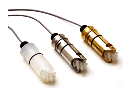
The turbine flow meters shown to the left are one form of this type of device. The cartridge unit is inserted into the flow stream with the shaft of the turbine unit parallel to the flow. This allows the flow across the angled turbine element to rotate in proportion to the flow across the blades. This device works well as long as the flow is not turbulent.
Since the meter is not actually measuring the full cross section of the flow, only the flow at a single point near the wall of the pipe, excessive turbulence will cause readings that are not representative of the real flow in the pipe.
As a result it is best to use these flow meters with caution and if you don’t have the real flow characteristics of the pipe, at least use the standard rule of thumb (20 / 10) for your distance from flow disturbances.
Like the Axial device, these flow measurement devices return a pulse output who’s frequency is proportional to indicated flow. This frequency is typically fed into a process meter which can be scaled to some particular set of engineering units.
Alternately if the intent is to use this with a data acquisition system, a counter / timer input should be used to read the frequency value. Also care should be taken to assure that you are using an appropriate output voltage range for the data acquisition input.
Credits - Mitchell Cottrell