An RTD sensor consists of more than just an element; the element is just part of a circuit that is made up of at least two and up to four lead wires, with any number of connectors and accessories. The circuit configuration can be dependent on a number of factors. Including:
• Distance between the sensing area and the instrumentation
• Temperature in the sensing environment across the length of the sensor
• Connection preferences
• Current wiring configuration e.g. a 4 wire sensor won’t be compatible with a 3 wire configuration
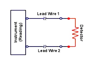
2-wire RTDs are the least accurate of the three circuit types as there is no way of calculating or eliminating the lead wire resistance between the detector and the reading. This creates uncertainty in the reading, so these sensors are often only used with short lead wires where accuracy is not of great importance. 2-wire Pt1000s can be used to reduce sensitivity and uncertainty but still don’t provide a true accurate reading.
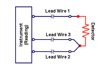
3-wire RTDs are the most commonly used RTD sensors. Assuming all three lead wires are the same the third lead wire calculates the average lead wire resistance throughout the circuit and removes it from the sensor measurement. This makes 3-wire RTDs more accurate than their 2-wire counterparts but less accurate than 4-wire configurations, however in circuits with long lead wires where there are long distances between the detector and the reading, significant savings can be made by using a 3-wire construction.
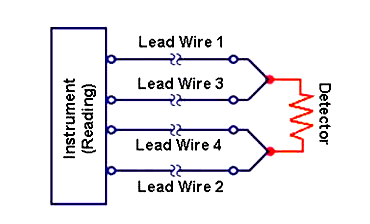
4-wire RTDs are used in applications where close accuracy is paramount. In a 4-wire RTD the actual resistance in each of the lead wires can be measured and eliminated leaving the exact resistance of the detector. The 4-wire circuit works by using the first two lead wires to power the circuit whilst the 3rd and 4th wires read the resistance in each lead wire compensating for any differences in lead wire resistance.
Reference : sterlingsensors