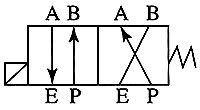
The solenoid valve has four ports that are labeled P (pressure), E (exhaust), A, and B. Notice the diagram symbol for the valve shows two boxes with the ports identified in one. It’s important to understand the physical valve has four ports identified as P, E, A, and B. The symbol for the valve shows the valve body two times to indicate the position of the valve passages when the coil for the valve is energized and when it’s de-energized:
In the diagram of the valve, the ports shown in the box near the coil indicate the position of the valve when the coil is energized. In this condition, the pressure port § is connected to the B port, which allows air to fill the cylinder and causes the rod to extend. It’s important to understand that the front port on the cylinder is connected to the A port, which is connected to the exhaust port (E) when the valve is energized. This allows a passage for the air in the front part of the cylinder to escape so the valve rod can move forward.
The diagram on the side of the valve near the spring symbol shows the position of the valve passages when the valve is de-energized. When the coil is de-energized, the spring moves the valve spool to a position where the pressure port § is connected to the A port and the exhaust port E is connected to the B port. This allows air pressure to enter the front of the cylinder and causes the rod to retract. The rear port of the cylinder is connected to the B port on the valve, which allows air to exhaust and the rod to retract.
One of the simplest types of final control devices in industrial circuits is the solenoid valve. The solenoid valve consists of a magnet coil and a movable armature. When the solenoid’s coil is energized, the armature is pulled up into the coil and the path for fluid to flow through the valve is open. When the coil is de-energized, spring tension forces the armature down so that the valve is closed off.
The coil of the solenoid valve is made of multiple turns of wire molded in the shape of a hollow core so that it fits around the armature. The coils of wire are encapsulated with epoxy for protection against moisture and heat, and two lead wires are provided for field connections. When the coil is energized, a strong magnetic field is developed and it pulls the armature into the middle of the coil.
When power is first applied to the coil, the amount of current drawn by the coil to begin building the magnetic field will be approximately three times the amount of current that is used after the armature moves to the middle of the coil. The initial current flow is called inrush current. The current that holds the armature in the energized position is called holding current.
If the coil is powered with DC voltage, an inductive voltage is created anytime power to the coil is de-energized. The inductive voltage is called an inductive kick and it is up to ten times the applied voltage and is in reverse polarity to the applied voltage. A diode or other type of suppression device must be connected across the coil of the solenoid to protect any other electronic components in the circuit that may be damaged by this voltage. The diode is connected in reverse bias across the DC solenoid coil so that when voltage is applied in normal polarity, the diode does not provide a path for current. When the solenoid coil is de-energized, the inductive voltage is the opposite polarity to the power supply, so it will flow through the diode and back into the coil. Since the coil is made of a large length of wire. the energy of the inductive voltage will be dissipated as it moves through the wire. This will render the excessive inductive voltage harmless. The fact that the inductive voltage will travel through the diode in the forward bias direction means the 0.7-1 volt drop across the diode junction will also limit the V=< (dv/dt) surge.
Since the armature physically moves inside the coil when power is applied to the coil, it will change the magnetic field, which will cause the current to drop to the holding-current level. If the armature did not move, the current would remain at the inrush level, which exceeds the current rating for the wire. The coil would quickly overheat and the wire would be burned until it caused an open. The level of the inrush current is determined by dividing the applied voltage by the resistance of the wire in the coil. This means that you should never connect voltage to a coil if it is not mounted on an armature. Some technicians test the coil by trying to pull the coil off the armature to see if it is magnetized. A problem occurs if the coil is pulled too hard and actually comes off the armature because the current will increase to the inrush level and cause the coil that is being tested to burn out. If the coil is tested with voltage, it is important that the coil is mounted over the armature.