The steam turbine-driven generators have auxiliary systems enabling them to work satisfactorily and safely. The steam turbine generator being rotating equipment generally has a heavy, large diameter shaft. The shaft therefore requires not only supports but also has to be kept in position while running.
To minimise the frictional resistance to the rotation, the shaft has a number of bearings. The bearing shells, in which the shaft rotates, are lined with a low friction material like Babbitt metal. Oil lubrication is provided to further reduce the friction between shaft and bearing surface and to limit the heat generated.
Barring gear
Barring gear (or “turning gear”) is the mechanism provided to rotate the turbine generator shaft at a very low speed after unit stoppages. Once the unit is “tripped” (i.e., the steam inlet valve is closed), the turbine coasts down towards standstill. When it stops completely, there is a tendency for the turbine shaft to deflect or bend if allowed to remain in one position too long.
This is because the heat inside the turbine casing tends to concentrate in the top half of the casing, making the top half portion of the shaft hotter than the bottom half. The shaft therefore could warp or bend by millionths of inches.
This small shaft deflection, only detectable by eccentricity meters, would be enough to cause damaging vibrations to the entire steam turbine generator unit when it is restarted. The shaft is therefore automatically turned at low speed (about one percent rated speed) by the barring gear until it has cooled sufficiently to permit a complete stop.
Condenser
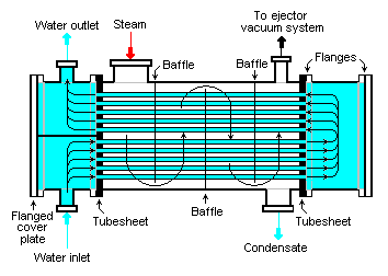
The surface condenser is a shell and tube heat exchanger in which cooling water is circulated through the tubes. The exhaust steam from the low pressure turbine enters the shell where it is cooled and converted to condensate (water) by flowing over the tubes as shown in the adjacent diagram. Such condensers use steam ejectors or rotary motor-driven exhausters for continuous removal of air and gases from the steam side to maintain vacuum.
For best efficiency, the temperature in the condenser must be kept as low as practical in order to achieve the lowest possible pressure in the condensing steam. Since the condenser temperature can almost always be kept significantly below 100 °C where the vapor pressure of water is much less than atmospheric pressure, the condenser generally works under vacuum. Thus leaks of non-condensible air into the closed loop must be prevented. Plants operating in hot climates may have to reduce output if their source of condenser cooling water becomes warmer; unfortunately this usually coincides with periods of high electrical demand for air conditioning.
The condenser generally uses either circulating cooling water from a cooling tower to reject waste heat to the atmosphere, or once-through water from a river, lake or ocean.
Feedwater heater
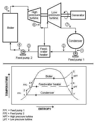
In the case of a conventional steam-electric power plant utilizing a drum boiler, the surface condenser removes the latent heat of vaporization from the steam as it changes states from vapour to liquid. The heat content (joules or Btu) in the steam is referred to as enthalpy. The condensate pump then pumps the condensate water through a feedwater heater. The feedwater heating equipment then raises the temperature of the water by utilizing extraction steam from various stages of the turbine.
Preheating the feedwater reduces the irreversibilities involved in steam generation and therefore improves the thermodynamic efficiency of the system. This reduces plant operating costs and also helps to avoid thermal shock to the boiler metal when the feedwater is introduced back into the steam cycle.
Superheater
As the steam is conditioned by the drying equipment inside the drum, it is piped from the upper drum area into an elaborate set up of tubing in different areas of the boiler. The areas known as superheater and reheater. The steam vapor picks up energy and its temperature is now superheated above the saturation temperature. The superheated steam is then piped through the main steam lines to the valves of the high pressure turbine.
Deaerator
A steam generating boiler requires that the boiler feed water should be devoid of air and other dissolved gases, particularly corrosive ones, in order to avoid corrosion of the metal.
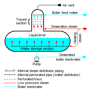
Generally, power stations use a deaerator to provide for the removal of air and other dissolved gases from the boiler feedwater. A deaerator typically includes a vertical, domed deaeration section mounted on top of a horizontal cylindrical vessel which serves as the deaerated boiler feedwater storage tank.
There are many different designs for a deaerator and the designs will vary from one manufacturer to another. The adjacent diagram depicts a typical conventional trayed deaerator. If operated properly, most deaerator manufacturers will guarantee that oxygen in the deaerated water will not exceed 7 ppb by weight (0.005 cm³/L).
Auxiliary systems
Oil system
An auxiliary oil system pump is used to supply oil at the start-up of the steam turbine generator. It supplies the hydraulic oil system required for steam turbine’s main inlet steam stop valve, the governing control valves, the bearing and seal oil systems, the relevant hydraulic relays and other mechanisms.
At a preset speed of the turbine during start-ups, a pump driven by the turbine main shaft takes over the functions of the auxiliary system.
Generator heat dissipation
The electricity generator requires cooling to dissipate the heat that it generates. While small units may be cooled by air drawn through filters at the inlet, larger units generally require special cooling arrangements. Hydrogen gas cooling, in an oil-sealed casing, is used because it has the highest known heat transfer coefficient of any gas and for its low viscosity which reduces windage losses.
This system requires special handling during start-up, with air in the chamber first displaced by carbon dioxide before filling with hydrogen. This ensures that the highly flammable hydrogen does not mix with oxygen in the air.
The hydrogen pressure inside the casing is maintained slightly higher than atmospheric pressure to avoid outside air ingress. The hydrogen must be sealed against outward leakage where the shaft emerges from the casing. Mechanical seals around the shaft are installed with a very small annular gap to avoid rubbing between the shaft and the seals. Seal oil is used to prevent the hydrogen gas leakage to atmosphere.
The generator also uses water cooling. Since the generator coils are at a potential of about 22 kV and water is conductive, an insulating barrier such as Teflon is used to interconnect the water line and the generator high voltage windings. Demineralized water of low conductivity is used.
Generator high voltage system
The generator voltage ranges from 11 kV in smaller units to 22 kV in larger units. The generator high voltage leads are normally large aluminum channels because of their high current as compared to the cables used in smaller machines.
They are enclosed in well-grounded aluminum bus ducts and are supported on suitable insulators. The generator high voltage channels are connected to step-up transformers for connecting to a high voltage electrical substation (of the order of 115 kV to 520 kV) for further transmission by the local power grid.
The necessary protection and metering devices are included for the high voltage leads. Thus, the steam turbine generator and the transformer form one unit. In smaller units, generating at 11 kV, a breaker is provided to connect it to a common 11 kV bus system.