We discuss about the Temperature Transmitter (RTD) Loop Checks Procedure. The loop checks for the temperature sensors, Resistance temperature detectors (RTD) are as follows.
RTD / Temperature Transmitter Loop Checks Procedure
-
Check and verify the DCS / ESD configuration for applicable points.
-
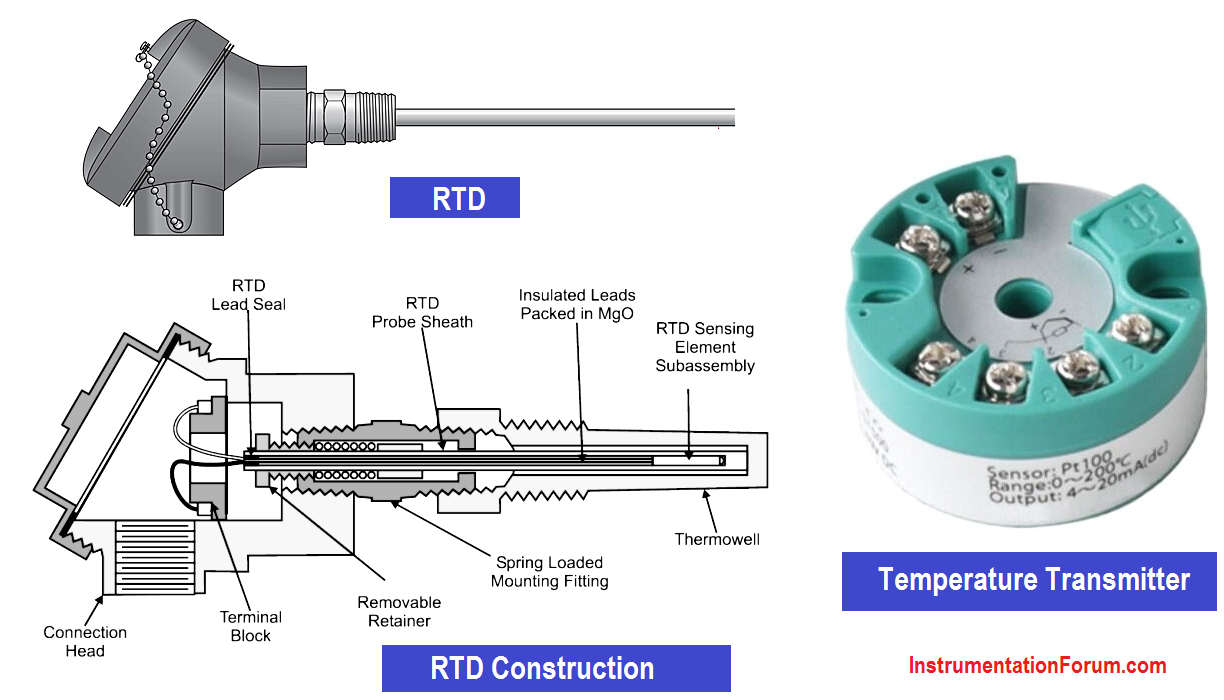
Simulate resistance equivalent to the 0%, 25%, 50%, 75% and 100% of the transmitter /DCS range, by using decade resistance box or any other resistance simulator at the RTD terminal head.
-
Verify the corresponding reading in the DCS / integral indicator of transmitter and remote indicator if applicable.
-
Alarm functions (in DCS) to be checked by simulating / varying the required signals.
-
Normalize all the connections prior to closing the terminal and confirm ambient temperature at integral indicator of temperature transmitter and in DCS. Special consideration shall be given to electrical connection of the RTD.
-
During loop checking, If the instrument is not accurate re –calibration should be done in calibration shop. Zeroing is not allowed.