THEORY OF MOTORIZED VALVE ACTUATOR CONTROLS
Limit torque Electrical Controls
Limitorque actuators allow valves to be remotely operated and, by use of a motor, allow rapid valve operation that otherwise would not be feasible.
This section deals with the control circuit and operation of the actuator in the motor mode. Although there are several power sources used in actuators, this section will be directed strictly to the use of electric motors.
Components
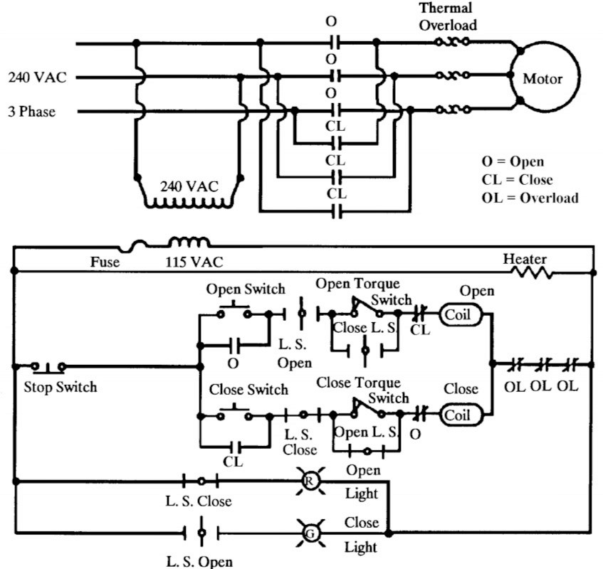
In the circuit, control power is transformed off incoming motor leads. The stop switch is normally closed
allowing a current flow path to exist up to the open and closed switches. The circuit as shown is deenergized with the valve in the full open position.
When the close direction switch (close switch) is closed, the closing coil of the Reversing Starter is energized. This will close the main line (motor leads) “CL” contacts to start the motor in the close direction, close the “CL” contact around the close switch (seal-in contact) and open the “CL” contact (electrical interlock contact) in series with the open coil.
The actuator will continue to position the valve in the close direction until the torque and/or limit switch detect binding or full stem travel, the respective contact will then open deenergizing the close coil which results in the main line contacts opening, the seal-in contact opening and the electrical interlock contact shutting.
The actuator can then be operated in the open direction in the same manner as described above. In the mid-position, the actuator can be operated in either direction.
Power Supply
The function of the power supply is to supply the energy required to operate the valve to which the actuator is attached. Although there are many sources of power, the Figure Typical Wiring Diagram assumption is made that 240 Volt Alternating Current (VAC), which is a typical selection, is the power source.
Motor
The function of the motor is to convert electrical power to mechanical power. Reversing any two of the three leads to the motor will result in a change in the direction of rotation.
The typical motor on Limitorque actuators is limited to a 15 minute duty cycle which must be considered when performing maintenance.
Overload Heater Coils
Overload heater coils (thermal overload relays) are a form of protection in the event of excessive motor current. Care must be exercised when sizing the heaters due to their time delay.
Reversing Starter
Reversing starters have two separate functions: 1) to interchange power leads which change the direction of rotation, and 2) to provide mechanical and electrical safety interlocks that prevent the contacts for both directions being closed at the same time which would cause a direct short between phases.
The operation of the reversing starter is based on using a small control current to control the larger motor current through electromagnetic switching. The coils shown in Figureoperate the main contacts of the starter when an open or close pushbutton is pushed. In addition, the seal-in contacts and contacts labeled “CL” and “O” are operated by the same coils in the reversing starter.
Control Transformer
The function of the control transformer is to reduce the control voltage to a lower andsafer level. Normally, the primary windings of the transformer is connected to two phases of the motor power.
The secondary windings provide the control voltage as single phase, normally 115 VAC. The primary side mayhave two fuses for protection, while the secondary side normally has one.
Stop Pushbutton(s)
The stop pushbutton(s) are always functional and are wired in series in the control circuit so that an operation by any one of them will open the circuit, which causes starter drop out and halts actuator operation.
They are a normally closed momentary open contact which de-energizes part of the circuit when pushed. Stop pushbuttons are usually located at each of the operating stations and locally at the actuator.
Open and Close Pushbuttons.
The function of the open and close pushbuttons is to initiate operation of the control circuit, which will result in energizing the actuator motor.
In typical applications,there are two sets installed - one at the valve (local) and one in the control room (remote). In some systems, only one set of open and close pushbuttons is energized at a time. See REMOTE/LOCAL switch.
Seal-in Contacts (Contactor Auxiliary Contacts)
The function of seal-in contacts is to allow the person operating the actuator to release the open and close pushbuttons without having the actuator stop. This allows electric controls to stop the operation automatically at a pre-set condition without operator intervention.
As an example, once energized, the actuator can be stopped by either the torque switch or limit switch depending on set-up of the valve-actuator. The seal-in contacts are labeled “O” and “CL” in Figure and are in parallel with either the open or closed switch.
Remote/Local Switch
This is a selector switch which determines the location of control for the
actuator. If the remote location is selected, the local control pushbuttons will not work.
Overload Contacts
The function of the overload contacts is to protect the circuit from an overload condition by interrupting the control circuit. The contacts are an integral part of the sensing heaters, normally 1 per phase. Great care must be exercised when working on equipment which is protected with heaters which reset automatically when they cool.
Some nuclear plants do not have protective heaters and some have them only when the actuator operates in a certain direction.
Electrical Interlock Contacts
The electrical interlock contacts, (contactor auxiliary contacts), prevent both the open and close contactors from operating at the same time. If the relay is protected by mechanical means, the electrical interlocks operate as a backup. The contacts are normally CLOSED contacts that open when the associated contactor operates.
The open auxiliary contact is wired into the close circuit, and the close auxiliary contact is wired into the open circuit. They are labeled “O” and “CL” in Figure and are in series with either the open or closed coils of the reversing starter.
Lights
The lights’ functions are to give approximate valve position information and as a useful tool for troubleshooting the actuator. The lights indicate the point where a particular rotor operates when activated by the limit switch, and is the same point where associated actions, if any, should be activated by contacts on the same rotor.
Normal operation has the open rotor turning off the red closed light and the close rotor turning off the green open light, with both lights on between the open and closed position. The contacts are normally aligned with the motor contacts on the rotor and are 90 degrees off from the spare and torque switch bypass contacts.
In actuators where the functions are divided by the use of additional rotors, (4 train limit switches) the lights may not function at the same time as the rest of the contacts. The lights may be driven by relays or actuated by external switches on the valve. There are many different control circuit arrangements.