Three Point Starter Working Principle
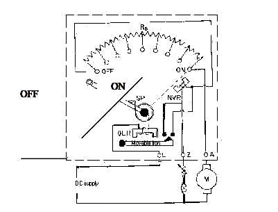
• The above figure shows, the motor is connected to supply terminals through three terminals L, A, and F available in the starter, it is called as three point starter.
• In this starter the resister elements are mounted behind an insulating board.
• The end of the resistor elements meet at the brass studs fixed on the front side of the board.
• The handle of the starter is fixed to a point so as to be moved over the studs against a spring tension.
• When the starter handle is moved and makes contact with first stud full voltage is applied to series combination of resistor elements and armature.
• Therefore a reduced voltage is applied to the armature due to drop in the resistor elements and starting current is limited to safe value.
• At the same time full voltage is applied across the shunt field and this establishes normal flux.
• As the starter handle is moved towards right from one stud to next stud the resistor elements are cut out one by one and the voltage applied to armature increases step by step.
• Finally when all the resistance elements are cut out the handle is in on position and full voltage is applied across the armature terminals.
• Now the current flowing through the no volt release coil develops an attractive force over the soft iron piece fixed to the starter handle.
• At normal voltage this attractive force holds the handle in on position against the spring tension at the pivoted end of the handle.
• When the applied voltage falls below certain value or at the interruption of supply voltage, the attractive force developed at the no volt release coil over the handle may not be sufficient to deep the handle in on position against the spring tension.
• Therefore the handle flies back to off position immediately and avoids restarting of motor on resumption of supply.
• If such arrangement is not there in the starter and the handle is on position, on resumption of supply full voltage would be applied to the armature terminals.
• Also, the voltage release coil is connected in series with the shunt field, the starter handle is released to off position whenever the field circuit be opened.
• This avoids racing or motor to high speed.
• The over load relay is connected in series with the armature circuit and carries load current.
• When motor is over loaded the current through over load relay increases. If this current exceeds a predetermined value, the mmf produced by the over load coil lifts the pivoted iron piece underneath the coil.
• This iron piece short circuits the no voltage release coil and destroy its attractive force over the handle.
• Therefore the handle is released to off position.
• When the handle moved to right and resistance elements are cut out, they are in turn, included in the field circuit.
• Since the resistance of these elements is very small, inclusion of them in the field circuit does not affect the field current appreciably.
• Another important point is that the armature and shunt field circuits are closed against each other through the starting resistor element even when the handle is in off position.
• Therefore the energy stored in magnetic circuit gets dissipated slowly through starting and armature resistances.
• Thus inductance is avoided.