Turbine Flow Meter
Turbine flow meters are volume counters operating on the Woltmann impeller counter principle. They record the flow rate in the flow-through in a pipe via the average flow velocity.
The flow of the medium is directed at the turbine wheel in the axial direction and so rotated. The speed of the freely turning wheel over a wide range is directly proportional to the average flow velocity.
The low weight of the turbine wheel ensures very short response times as well as very dynamic behaviour in flow changes. Two flow straighteners generate quasi-laminar flow, which in turn contributes to increasing the measurement accuracy.
The speed of the turbine wheel is tapped by the contactless sensor technology (transducer) through the housing wall. The sensor system can be variably adapted to meet the requirements of the respective application.
This also allows, for example, providing a signal to indicate the direction of flow. Pulses per unit of volume are available for analysis. The calibration factor (K-factor) of the flow meter describes the exact pulse rate per unit of volume. In order to determine the individual calibration factor of a flow meter, we calibrate each of our meters in house prior to delivery.
The operating viscosity specified by the customer is taken into account for calibration. A corresponding calibration certificate is included with every flow meter we supply. The turbines feature a short response time between 5 and 50 ms depending on the nominal width, which is advantageous for precise filling processes.
Turbine flow meters have a resolution of up to 100,000 pulses per litre. The milled and turned precision components are the reason why the HM series has neither wetted weld seams nor soldered connections.
Calibration
In-house calibration is performed on volumetric calibration rigs/units.
The calibration lab uses a high-precision load cell system. With an accuracy of 0.05 % for the mass and 0.1 % for the volume of flowing liquids, we occupy a leading position worldwide.
The calibration certificate not only verifies the accuracy of a flow meter, but also guarantees its traceability to national standards as well as ensuring all requirements according to international quality standards are met.
The calibrations are performed with different hydrocarbons. This ensures the optimum simulation of changing operating conditions in density and viscosity even when temperatures change.
This way the primary viscosity for the use of the flow meter can be specifically taken into account when viscosity fluctuations occur.
The calibration result is the specified calibration factor (K-factor) in pulses per litre. This K-factor accordingly applies only at a certain flow velocity or a certain flow rate.
The calibration factor varies only very slightly at different volume flow rates.
The individual measuring points provide the calibration curve of the flow meter from which the average K-factor is determined.
The average calibration factor applies to the entire measuring range. The linearity error specification (percentage deviation) refers to the average K-factor.
To further increase the measurement accuracy in onsite use, the specific K-factors can be used to calculate the flow rate.
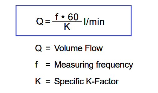
Calculation of volume flow
The flow is directly dependent on the measured frequency and the associated calibration factor:
>> Turbine Flow meter Animation : Check Here
Source : kem-kueppers