Current loop circuits are one possible way used to control radio base stations at distant sites. The two-way radio industry calls this type of remote control DC remote. This name comes from the need for DC circuit continuity between the control point and the radio base station. A current loop remote control saves the cost of extra pairs of wires between the operating point and the radio transceiver. Some equipment, such as the Motorola MSF-5000 base station, uses currents below 4 mA for some functions. An alternative type, the tone remote, is more complex but requires only an audio path between control point and base station.
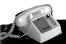
Figure : A Motorola T-1300 series remote control is built in a telephone housing. The dial is replaced with a speaker and volume control. This remote control uses a two-wire circuit to control a base station.
For example, a taxi dispatch base station might be physically located on the rooftop of an eight-story building. The taxi company office might be in the basement of a different building nearby. The office would have a remote control unit that would operate the taxi company base station over a current loop circuit. The circuit would normally be over a telephone line or similar wiring. Control function currents come from the remote control console at the dispatch office end of a circuit. In two-way radio use, an idle circuit would normally have no current present.
In two-way radio use, radio manufacturers use different currents for specific functions. Polarities are changed to get more possible functions over a single circuit. For example, imagine one possible scheme where the presence of these currents cause the base station to change state:
no current means receive on channel 1, (the default).
+6 mA might mean transmit on channel 1
−6 mA might mean stay in receive mode but switch to channel 2. So long as the −6 mA current were present, the remote base station would continue to receive on channel 2.
−12 mA might command the base station to transmit on channel 2.
This circuit is polarity-sensitive. If a telephone company cable splicer accidentally reversed the conductors, selecting channel 2 would lock the transmitter on.
Each current level could close a set of contacts, or operate solid-state logic, at the other end of the circuit. That contact closure caused a change of state on the controlled device. Some remote control equipment could have options set to allow compatibility between manufacturers. That is, a base station that was configured to transmit with a +18 mA current could have options changed to (instead) make it transmit when +6 mA was present.
In two-way radio use, AC signals were also present on the circuit pair. If the base station were idle, receive audio would be sent over the line from the base station to the dispatch office. In the presence of a transmit command current, the remote control console would send audio to be transmitted. The voice of the user in the dispatch office would be modulated and superimposed over the DC current that caused the transmitter to operate.